NAT & PAT Technology
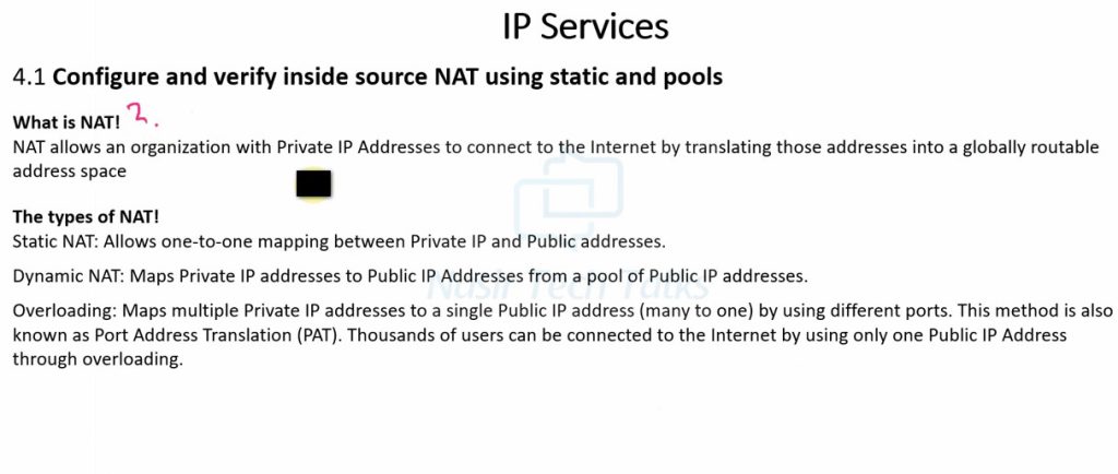
What is NAT
The problem with IPv4 addresses
An IP address is used as an endpoint identifier in IP-based communications. It is just like a telephone number. When you want to call another person over your mobile, you dial his telephone number. The call is established between phone numbers.
In the same way, when a device wants to communicate using IP communication, it sends the data to the remote end’s IP address. The communication is established between IP addresses. Every mobile phone has a telephone number. In the same way, every device needs an IP address to send and receive data over an IP network.
IPv4 addresses are limited number. A key point here is that, by standard, an IPv4 address is 32 bits long, meaning there are only 4,294,967,296 possible unique IP addresses (and they were officially exhausted in April 2017). That’s it; new addresses could never be produced. The IPv4 address space is a finite resource.
The original idea when the Internet protocol was first introduced was that every organization would ask for and be given an IP address range, and IP addresses would be unique and not reused. People thought we had so many IPv4 addresses (4 billion) that everybody would have a unique IP that nobody else uses anywhere on the planet.
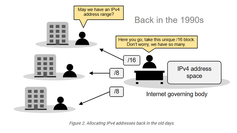
So, the Internet governing body was giving big, classful blocks of IP addresses (/8, /16, or /24) to every organization that asked for it. This model worked for a while. However, in the mid-1990s, it became extremely evident that the Internet was growing so fast that we would run out of addresses in a few years.
Then, people realized we needed a new IP protocol that supported more addresses, so IPv6 was introduced. This protocol uses 128-bit addresses instead of 32-bit, allowing for 2128 addresses. However, most organizations had already invested a lot of money in the adoption of IPv4. They were unwilling to reinvest time and money to migrate to IPv6, so they were looking for another solution.
The solution came through combining two network standards that worked together to save IPv4 address space: Private IPv4 addresses (RFC1918) and Network Address Translation (NAT).
The private IPv4 space (RFC1918)
If we combine the following two statements:
- Every device must have an IP address to communicate over the Internet.
- IPv4 addresses are finite (4 billion overall, but significantly less usable).
It is evident that, at some point, there will not be enough IPv4 addresses for every device on the planet. To overcome this problem, people came up with a brilliant idea:
- Can’t we reuse some portion of the IPv4 address space wherever required?
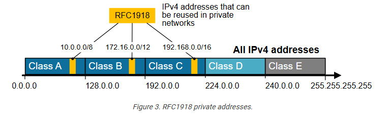
And that’s how the private IPv4 address space was born. A small portion of each class of usable IPv4 addresses was dedicated to addressing inside private networks (highlighted in yellow in the diagram below). These addresses were called private IP addresses and can be used anywhere by anyone without permission. They are not subject to IANA allocation.
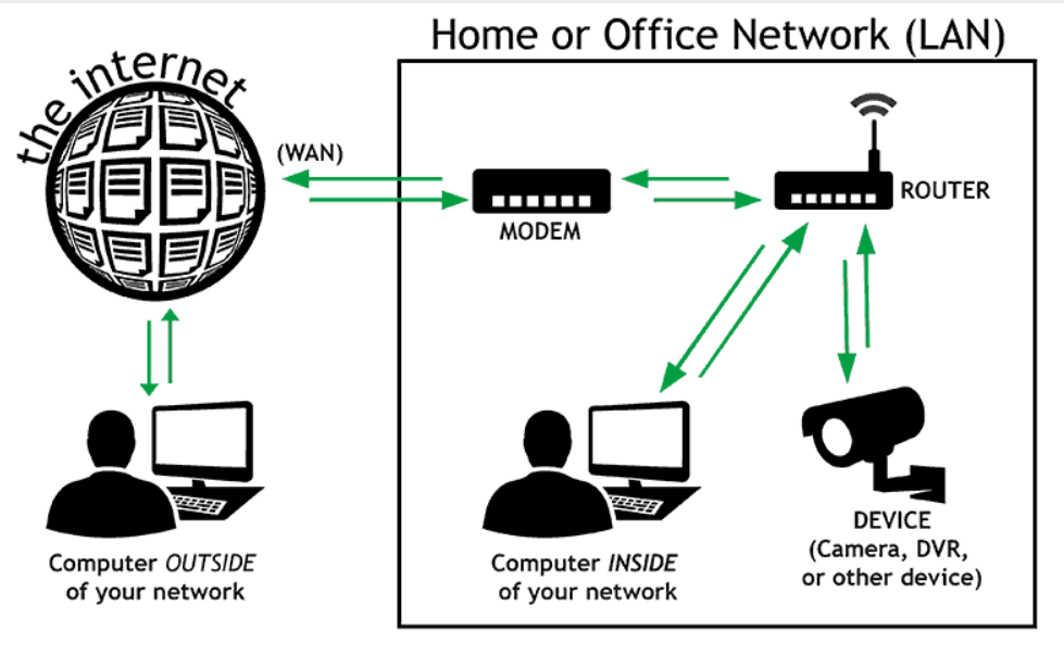
IPv4 private addresses are not routable on the public Internet. These addresses are typically used within internal networks (e.g., home, office, or enterprise environments), and devices with private IP addresses can communicate within that network. However, they must pass through a device like a router performing Network Address Translation (NAT) to access the Internet.
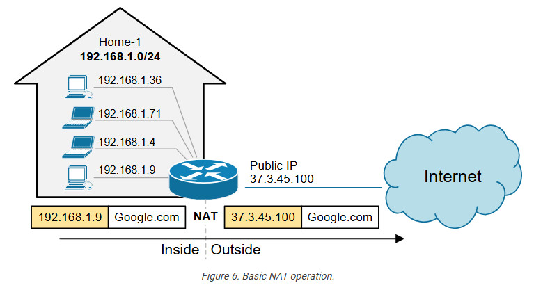
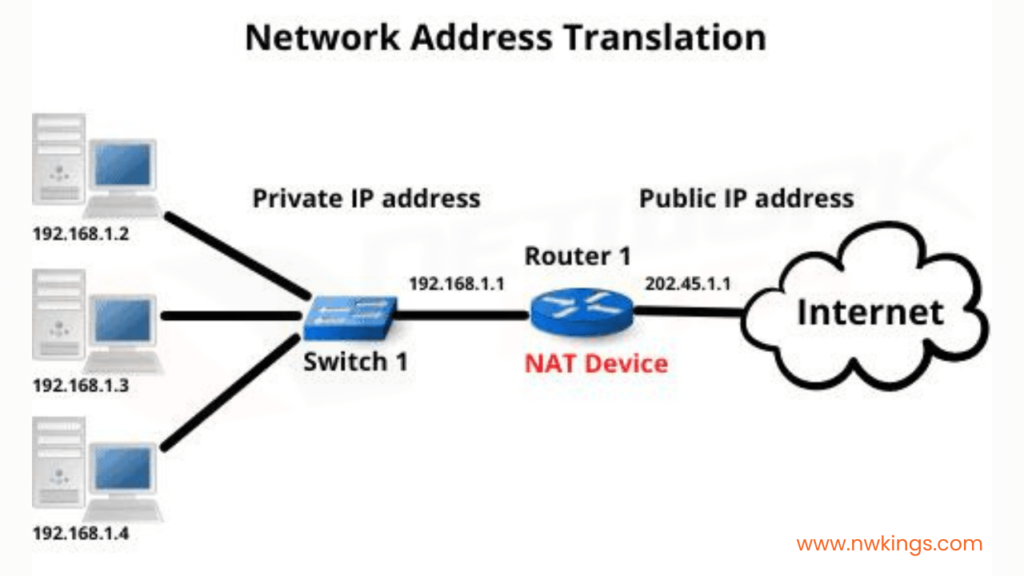
Every home network in the diagram below uses the same private network 192.168.1.0/24. For example, every device inside Home-1 has a private IPv4 address. However, when a device communicates with a host on the Internet, its address is translated into a public address assigned to the Internet router (37.3.45.100). All devices in Home-1 share this public IPv4 address when talking to the Internet.
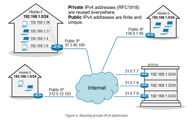
The idea is that anyone can use these addresses or re-use them for as many hosts as they like on their internal network. NAT can then translate the multitude of hosts using Private addresses into a much smaller set of Public addresses – thereby curbing the rate at which IPv4 addresses are being utilized.
What is NAT?
Network Address Translation (NAT) is a network capability that allows a device (typically a router or a firewall) to modify the IP address information in the IP packet headers while in transit. For example, let’s look at the diagram shown below. PC2 is configured with the private IPv4 address 192.168.1.5. This address is not routable on the Internet. However, PC2 can access the Internet because the router does Network Address Translation (NAT). When PC2’s packets reach the router, the router changes the source IP address in the IP header from 192.168.1.5 to 37.3.45.7, as shown in the diagram. Hence, all devices on the Internet see PC2’s traffic as coming from the public IP address 37.3.45.7.
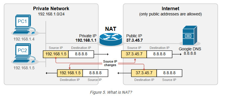
NAT is most commonly used to enable multiple devices on a private network to access the internet using a single public IP address, which helps conserve the limited number of IPv4 addresses available. For example, all devices inside Home-1, as shown in the diagram below, use private IPv4 addresses from subnet 192.168.1.0/24. The router translates all internal IP addresses to the public IPv4 address assigned to the interface that connects to the Internet. Devices on the Internet see all traffic from Home-1 as coming from the public IP address 37.3.45.100.
You can see that NAT and private IPv4 addresses work together to conserve IPv4 address space by allowing many devices in a local network to share a single public IPv4 address. Without NAT and private IPv4 addresses, every device inside Home-1 would have required a unique public IP address. This would have depleted the available IPv4 addresses would long ago due to the rapid growth of devices connected to the internet.
Static NAT
A device, such as a router or firewall, can change the IP address information in the packets’ headers while packets pass through. This network function is called Network Address Translation (NAT) and is shown in the diagram below.
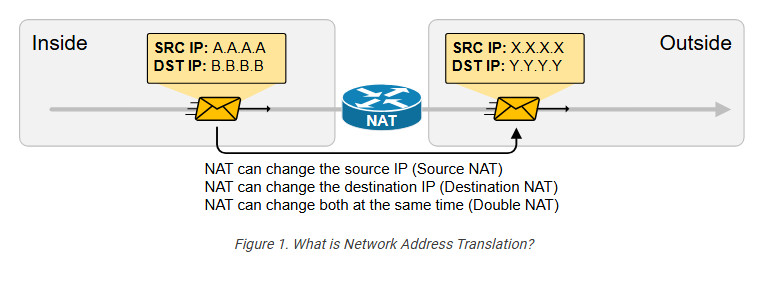
We have a packet with source IP “A.A.A.A” and destination IP “B.B.B.B” that goes through address translation. After the packet passes through the router, it has source IP “X.X.X.X” and destination IP “Y.Y.Y.Y.”
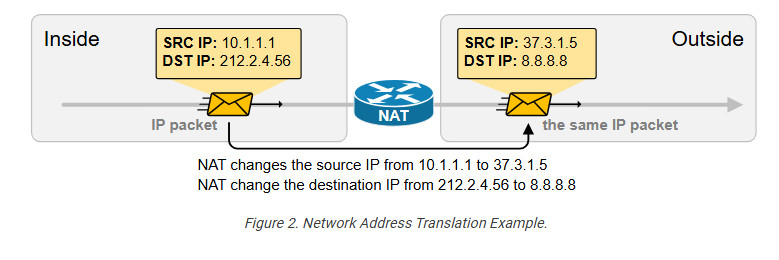
The following diagram shows an example of NAT with real IPv4 addresses. Notice something fundamental. Typically, organizations use NAT to translate private IPv4 addresses into public IPv4 addresses. However, from NAT’s perspective, it doesn’t matter whether the IPs are public or private. NAT can translate any IPv4 address to any other IPv4 address, whether private or public. In the example below, the NAT router translates the source IPv4 10.1.1.1 to 37.3.1.5 (private to public) and the destination IPv4 address 212.2.4.56 to 8.8.8.8 (public to public).
NAT is so ubiquitous and well-accepted that organizations primarily use private IPv4 addresses inside the entire network. Then, they use a small number of public IPv4 addresses on the internet-facing devices and use NAT to translate between the two, as shown in the diagram below.
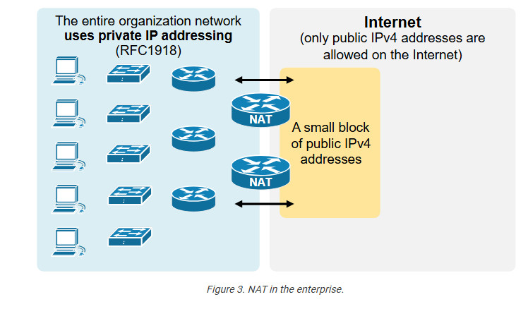
an change a packet’s source, destination, or both source and destination IP addresses while it passes through a router or a firewall. In 99% of implementations, NAT changes only the packet’s source address, which is typically private, with a public IPv4 address. This process is referred to as source NAT because only the source IP address is being changed (the destination IP address in the packet is left untouched).
Static Source NAT
Static NAT is the most straightforward type of network address translation. An IPv4 address on the inside is always mapped to the same IPv4 address on the outside via a configuration command. For example, the IP address 10.1.1.1 is always replaced with 37.3.1.1 when a packet goes through the NAT router, as shown in the diagram below.
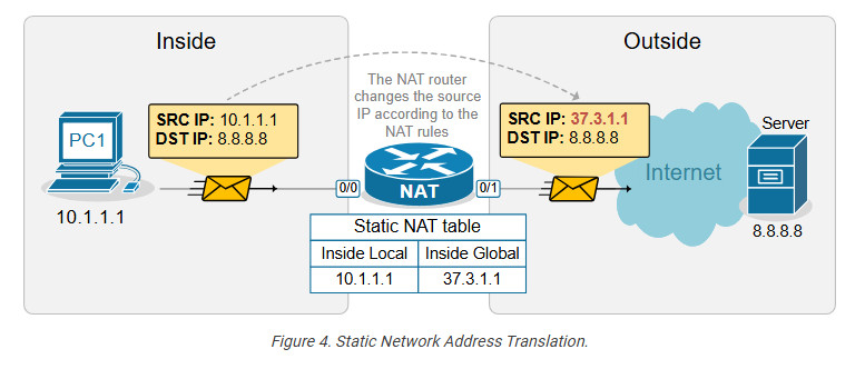
This static NAT rule allows PC1 to access the Internet because Internet hosts see PC1’s traffic as coming from public IP address 37.3.1.1. However, if a second PC must access the Internet, we need a second public IPv4 address and a second static NAT rule.
For example, if we have three PCs, as shown in the diagram below, we need three public IPv4 addresses and three static NAT rules. However, notice that the public IPv4 subnet assigned on the outside interface of the router is /26, which means we can only have 64 addresses. If we have 100 hosts on the inside, we cannot configure a static one-to-one mapping for all of them because we only have 64 public IPv4 addresses on the router’s outside interface.
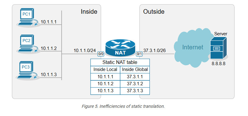
This example outlines the following essential aspects of Static NAT.
- It is a static mapping between an Inside Local and Inside Global address, as shown in the diagram above (more on these terms later on).
- It does not conserve IPv4 addresses.
- It does not scale.
You may be wondering why this network translation technique even exists if it doesn’t conserve IP addresses. The truth is that static NAT is typically not an organization’s primary network translation technique. For most hosts with private IPv4 addresses, the organization most likely uses Dynamic NAT with Overload (more on it in the following lessons). Static NAT is typically used only for some particular IP addresses assigned to special hosts. Here are some reasons why:
- It is a predictable, consistent one-to-one mapping.
- It allows hosts on the outside to initiate connections to the inside. This one is key.
With static NAT, a specific internal private IP is always mapped to a specific public IP, making the translation predictable. This is useful for services that need to be consistently reachable from the outside, such as Web servers, Mail servers, and VPN gateways. For example, we have a web server inside the organization that has a private IPv4 address, 10.1.1.3, as shown in the diagram below.
Configuring Static NAT
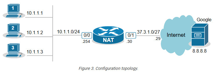
Let’s now see how to configure a router to perform static source network address translation. We will use a very basic topology, which you can download from the section at the end of the lesson and practice yourself.
The configuration process can be broken down into two main steps that are independent of one another:
Step 1. Defining Inside and Outside from the point of view of the local router.
Step 2. Configuring the NAT rules.
Step 1. Defining Inside and Outside
The first step in configuring network address translation is the same for every type of NAT – the router must identify which interfaces connect to the Inside which to the Outside.
A router cannot independently determine which interfaces connect to the organization’s network and which connect to an external network such as the Internet. For the router, every interface is the same—a layer 3 port with an IP address.
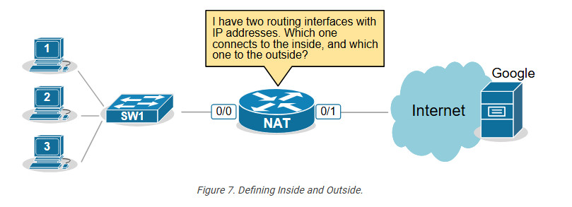
That’s why we must explicitly define the NAT zones on the router as follows:
- We must explicitly tell the router which interfaces connect to the Inside. The inside is typically our organization, an enterprise, a small office, or a home. This is our network, where we use private IPv4 addresses.
- We must explicitly tell the router which interfaces connect to the Outside. The outside is typically the Internet, but it can also be another external network. This is the network where typically only public IPv4 addresses are allowed.
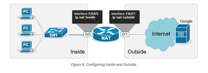
For example, we explicitly tell the router shown in the diagram above that its interface Ethernet0/0 connects to the Inside and Eth0/1 connects to the Outside by applying the configuration shown in the output below.
					interface range Ethernet0/0
ip address 10.1.1.254 255.255.255.0
ip nat inside
!
interface Ethernet0/1
ip address 37.3.1.254 255.255.255.0
ip nat outside
!
Notice that a router may have multiple interfaces connecting to the Inside and multiple interfaces connecting to the Outside.
Step 2. Configuring NAT rules.
The second step in the configuration process is to define the network address translation rules. The following diagram shows the rules we need to configure.
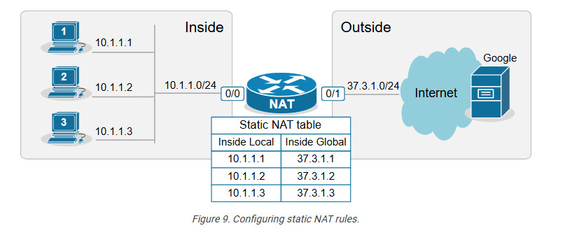
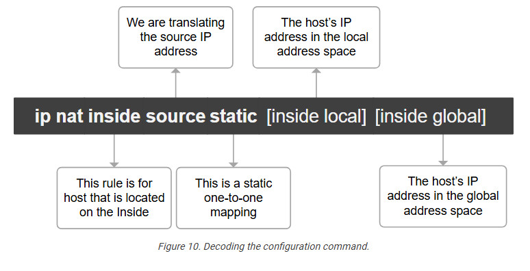
We apply one configuration command in global configuration mode for every one-to-one mapping, as shown in the output below.
					ip nat inside source static 10.1.1.1 37.3.1.1
ip nat inside source static 10.1.1.2 37.3.1.2
ip nat inside source static 10.1.1.3 37.3.1.3
We have configured static network address translation for each local host in the topology. Now, let’s verify that the hosts can reach the Google server.
Verifying the network address translation
We use the following command to verify that the network address translation is working. Notice the terms “Inside local,” “Inside global,” “Outside local,” and “Outside global.”
					NAT# sh ip nat translations

Pro Inside global Inside local Outside local Outside global
icmp 37.3.1.1:3 10.1.1.1:3 8.8.8.8:3 8.8.8.8:3
--- 37.3.1.1 10.1.1.1 ---
It is essential to understand what each of those terms means, so let’s zoom in.
Decoding the NAT table
One of the most important goals of this lesson is to ensure you understand the four main NAT table terms:
- inside Local
- Inside Global
- Outside Local
- Outside Global
Let’s use the diagram below to introduce the key terms. Notice that we have a static one-to-one mapping that allows the host 10.1.1.1 on the inside to reach the host 8.8.8.8 on the Internet.
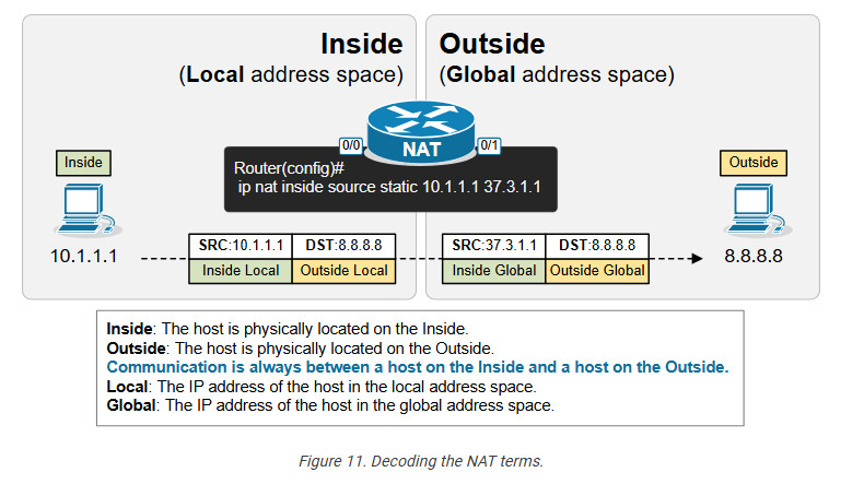
First, remember that from the perspective of the NAT router, every communication is between a host on the Inside and a host on the Outside. (Having in mind that Inside and Outside are already defined using the ip nat inside/outside command). One host is referenced as Inside and the other as Outside, as shown in the diagram below.
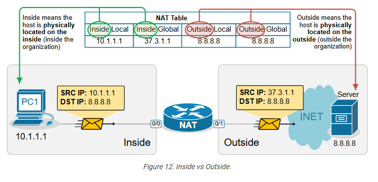
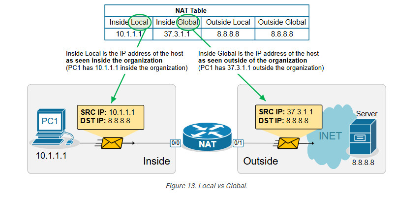
- In that context, the term “Inside Local” refers to the host’s IP address in the local address space. Typically, this is a private IPv4 address of a host inside the organization. For example, PC1 is seen with IP address 10.1.1.1 inside the local network.
- The term “Inside Global” refers to the host’s IP address in the global address space. Typically, this is the public IPv4 address representing the host outside the organization. For example, PC1 is seen with IP address 37.3.1.1 on the Internet.
The following diagram visualizes the difference between the Local and Global terms.
Static address translation can be configured in the opposite direction for the host on the outside. The Outside host with Outside Global address 8.8.8.8 can be represented with an Outside Local address 10.1.1.8 on the inside, depending on the network requirements.
Another useful NAT verification tool is the show ip nat statistics command. It clearly shows the inside and outside interfaces and the type of NAT rules that are configured.
Key takeaways
- One-to-One Mapping: Static NAT creates a permanent, one-to-one mapping between a local (private) IP address and a global (public) IP address.
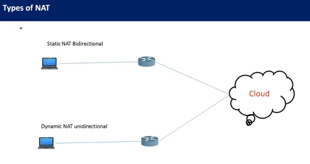
- Bidirectional Communication: It allows both inbound and outbound traffic, meaning external hosts can reach internal devices using the global IP, and internal devices can access external networks using the same IP mapping.
- Static Configuration: The NAT translation is manually configured and remains static until removed, which is ideal for servers requiring consistent public IP addresses.
- Use Cases: Often used for scenarios where certain internal resources (e.g., web servers) need to be consistently accessible from the internet.
- No Port Translation: Static NAT does not modify ports; it only translates IP addresses. This contrasts with PAT (Port Address Translation), which maps multiple private IPs to a single public IP using different ports.
Dynamic NAT
This lesson continues our discussion on Network Address Translation by examining Dynamic NAT. At the end of the lesson, you can download the EVE-NG virtual machine and practice the configurations on your own.
What is Dynamic NAT?
Dynamic NAT is basically a static one-to-one mapping between an inside local and inside global that happens automatically. We have seen in the previous lesson that with Static NAT, a network administrator manually configures every one-to-one mapping on the router. For example, to map the inside local address 10.1.1.1 to inside global 37.3.1.1, a network admin must configure the following configuration line on the rou
Router(config)# ip nat inside source static 10.1.1.1 37.3.1.1
Suppose there are many inside local and inside global addresses. In that case, the network admin must configure many configuration lines on the router and statically pair each inside local and global addresses.
Dynamic NAT is a method of dynamically mapping inside local addresses (typically private ones) to inside global IP addresses (typically public ones) from a predefined pool of global IPs. Unlike Static NAT, where there’s a fixed one-to-one mapping between local and global addresses, Dynamic NAT maps local to global addresses on a first-come, first-served basis.
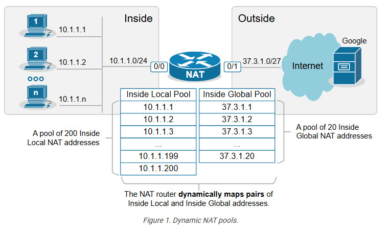
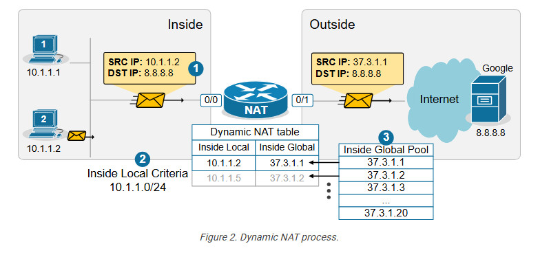
Let’s see how Dynamic NAT works in a few steps, as visualized in the diagram below:
- Step 1. A host on the inside, PC2(10.1.1.2), sends traffic destined for the Internet (8.8.8.8).
- Step 2. The router receives the packet on its NAT-Inside interface, meaning it must translate the source address according to the configured NAT rules. The source IP matches the Inside Local criteria (it is part of subnet 10.1.1.0/24).
- Step 3. Since the router is configured to translate the source address from 10.1.1.0/24 to the configured NAT pool, the router maps the host’s private IP address (Inside Local) to the first available public IP address from the NAT pool (Inside Global). The router creates a one-to-one mapping between PC2’s private address (10.1.1.2) and the first available public IP address from the NAT pool (37.3.1.1), as shown in the diagram below.
When step 3 is complete, the router adds a dynamic entry in its NAT table for the pair (10.1.1.2, 37.3.1.1) and keeps the entry until traffic flows between the PC2 and the host on the Internet. As long as the entry exists in the table, only host 10.1.1.2 can use the public address 37.3.1.1. The default timeout for the dynamic entry is 24 hours. IIf no traffic is seen in 24 hours, the entry is deleted from the table, and the public IP address is returned to the NAT pool.
Suppose another host, PC5 (10.1.1.5), sends packets destined for the Internet at the same time. The NAT router performs the same steps and dynamically maps the PC5’s private address, 10.1.1.5, to the next available public address from the pool – 37.3.1.2, as shown in the diagram above. The router keeps mapping Inside Local addresses to the next available Inside Global address until all addresses in the NAT pool are allocated. Then, if a packet arrives and there are no available public IPv4 addresses in the pool, the router discards the incoming packet. The size of the pool defines the maximum number of inside hosts that can access the Internet at the same time.
Notice the following key aspects of Dynamic NAT:
- Many-to-Many Mapping: Private IP addresses are mapped to public IPs dynamically from a pool, meaning there is no fixed assignment.
- Temporary Mapping (24 hours by default): The public IP is assigned to a private IP only when traffic is sent out and released when the session ends.
Configuring any network address translation starts with identifying the Inside and Outside interfaces of the router. In this example, we configure the Eth0/0 interface as Inside and the Eth0/1 interface as outside, as shown in the output below.
					interface Ethernet0/0
ip address 10.1.1.254 255.255.255.0
ip nat inside
!
interface Ethernet0/1
ip address 37.3.1.30 255.255.255.224
ip nat outside
!
The next step is configuring an access list defining the Inside Local criteria. Basically, when a packet enters the router on the NAT-inside interface, the router will check whether the source IP address is from the configured subnet. In our example, we will translate the source addresses from subnet 10.1.1.0/24 so the ACL looks like this:
					ip access-list standard INSIDE_LOCAL
10 permit 10.1.1.0 0.0.0.255
!
Then, we need to define the pool of Inside Global addresses. In our case, we are given the range of addresses 37.3.1.1-37.3.1.20, so we configure the pool as follows:
ip nat pool INSIDE_GLOBAL 37.3.1.1 37.3.1.20 prefix-length 27
Lastly, we configure the NAT rule. Notice that the command references the access list and the pool that we have just configured.
ip nat inside source list INSIDE_LOCAL pool INSIDE_GLOBAL
The command basically tells the router – “When a packet arrives on your inside interface, and the packet’s source address matches the Inside Local criteria (10.1.1.0/24), map it to the next available public IPv4 address from the Inside Global pool.”
Verifying Dynamic NAT
Immediately after the router has been configured, its NAT table is empty. We must first initiate some traffic from Inside to Outside in order to trigger the dynamic translation. Let’s ping from the hosts to the Google server.
					PC1> ping 8.8.8.8
Type escape sequence to abort.
Sending 5, 100-byte ICMP Echos to 8.8.8.8, timeout is 2 seconds:
.!!!!
Success rate is 80 percent (4/5), round-trip min/avg/max = 1/2/6 ms
PC2> ping 8.8.8.8
Type escape sequence to abort.
Sending 5, 100-byte ICMP Echos to 8.8.8.8, timeout is 2 seconds:
.!!!!
Success rate is 80 percent (4/5), round-trip min/avg/max = 1/4/7 ms
PC3> ping 8.8.8.8
Type escape sequence to abort.
Sending 5, 100-byte ICMP Echos to 8.8.8.8, timeout is 2 seconds:
.!!!!
Success rate is 80 percent (4/5), round-trip min/avg/max = 1/3/8 ms
Now if we check the network translation table using the following command, we can see the dynamic one-to-one mappings.
					NAT# sh ip nat translations
Pro Inside global Inside local Outside local Outside global icmp 37.3.1.1:14 10.1.1.1:14 8.8.8.8:14 8.8.8.8:14 --- 37.3.1.1 10.1.1.1 --- --- icmp 37.3.1.3:2 10.1.1.2:2 8.8.8.8:2 8.8.8.8:2 --- 37.3.1.3 10.1.1.2 --- --- icmp 37.3.1.2:1 10.1.1.3:1 8.8.8.8:1 8.8.8.8:1 --- 37.3.1.2 10.1.1.3 ---
Notice the Hits and Misses counters. The Hits counter shows how many packets arrived on the router’s inside interface and required address translation. Those packets were able to be translated. However, the Miss counter is more important. It shows how many packets arrived, and the router could not translate them to an Inside Global address because there were no available IPv4 addresses in the Inside Global pool. The counter is zero in our example because we have only three internal hosts but 20 available Inside Global addresses. However, you must keep track of this counter in a real-world implementation.
Key Takeaways
Dynamic NAT is a method of dynamically mapping private IP addresses to public IP addresses from a predefined pool of public IPs. Unlike Static NAT, which uses a fixed one-to-one mapping between private and public addresses, Dynamic NAT maps private addresses to public ones as needed on a first-come, first-served basis. When the pool of public IPs runs out, additional private hosts cannot access the Internet until a public IP becomes available.
Compared to Static NAT:
- Static NAT requires one public IP for each internal device at all times, even if the device isn’t currently communicating. Dynamic NAT allocates public IPs only when needed, which can be more efficient when public IPs are limited.
- Dynamic NAT scales better than Static NAT when many internal devices need internet access, but not all at once. It reduces the number of required public IP addresses by assigning them dynamically rather than having a static one-to-one mapping.
Compared to PAT (Port Address Translation):
- Some applications (like VoIP or certain security protocols) may require consistent port usage without translation, which is problematic with PAT. Dynamic NAT avoids this by mapping only the IP addresses, leaving the ports unchanged.
- Since Dynamic NAT assigns a unique public IP from the pool, it’s easier to track which internal device is using which public IP at a given time. PAT’s port-based mappings can make tracing connections back to a specific internal device harder.
NAT Overload (PAT)
Port Address Translation (PAT), also known as NAT overload, is a type of Network Address Translation (NAT) that allows multiple devices on a local network (with private IP addresses) to share a single public IP address to access external networks, such as the internet.
However, to really understand how PAT works, you must know how TCP/UDP connections are established in the context of IP addresses and ports. Let’s quickly refresh our knowledge of sockets and TCP sessions.
What is a socket, and what is a TCP session?
In networking, a socket is an endpoint for sending and receiving data between devices over a network. It provides a mechanism for communication between two hosts, typically a client and a server, enabling applications to exchange data over protocols like TCP or UDP.
A socket is a pairing between an IP address and a port, as shown below:
IP_Address:Port_Number
When two applications communicate, they each create a socket. A connection between them is established by pairing the client socket with the server socket, forming a TCP or UDP session.
A TCP session is always between two sockets. For example, on Windows, you can see the established sessions between the host and remote hosts using the netstat command, as shown in the output below.
					netstat -a -n | find /I "ESTABLISHED"
TCP 10.1.1.1:43000 65.3.2.1:443 ESTABLISHED
TCP 10.1.1.1:43001 65.3.2.1:443 ESTABLISHED
TCP 10.1.1.1:43002 65.3.2.1:443 ESTABLISHED
Notice that a pair of one local and one remote socket uniquely describes a TCP/UDP connection. For example, one unique TCP session is (10.1.1.1:43000-65.3.2.1:443). If host 10.1.1.1 wants to establish a new TCP connection to the same server, it must use another TCP port like this: (10.1.1.1:43001-65.3.2.1:443). The logic is visualized in the diagram below. Notice that PC has established three TCP sessions with the same server. Pay attention to the IP addresses and ports (sockets).
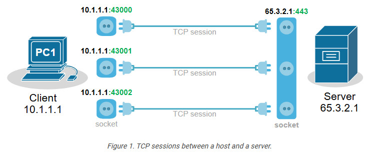
Notice another important aspect. In client-server communications, the server socket is always the same. The server’s web hosting service always listens on the same socket (IP:Port), typically on port 80(http) or 443(https). Therefore, the client-side socket distinguishes the different TCP connections to the server.
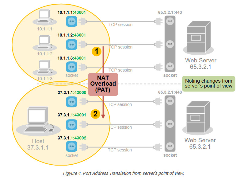
Every TCP session is between a pair of sockets. The combination of local and remote sockets is unique because the host uses a different TCP port for each connection. Let’s see a slightly different example – three different hosts establishing a single connection to the same server.
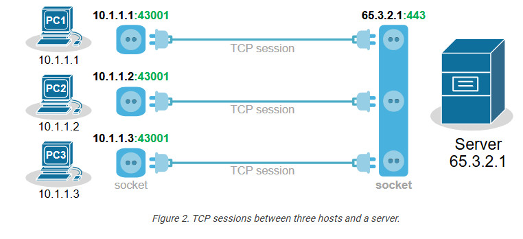
Notice that each host uses the same TCP port. So, how does the server differentiate between the three sessions? Each host’s IP address is different, which makes the three TCP sessions unique from the server’s point of view.
Now, let’s compare the two scenarios from the webserver’s perspective. Do you see any difference in the context of sockets and TCP sessions?
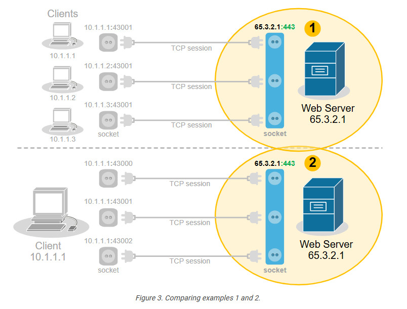
No, from the server’s point of view, there is no difference. In client-server communications, the clients choose a random port and initiate the connection. The server always listens for connection on the same socket. The server does not differentiate between three TCP sessions to one host and three TCP sessions to three different hosts. For the server, these are just three TCP sessions.
What is Port Address Translation (PAT)?
People soon realize they can use this to their advantage and translate multiple clients’ private IP addresses to one public IPv4 address by changing the entire socket (IP:port), not only the IP address. For example, we can change the sockets (IP:port) of the three hosts with different sockets with the same public IPv4 address but different ports. This wouldn’t change anything on the server side
Of all Network Address Translation types, PAT is by far the most popular and widely adopted one. Every home WiFi router and every small, medium, and large enterprise uses PAT. It can translate up to 65000 private IPv4 addresses to a single public IPv4 address. It reduces the need for multiple public IP addresses, which can be costly for organizations with many devices.
On the other hand, PAT has some disadvantages as well. It only works for clients in client-server communication (which accounts for 99% of the Internet traffic). It complicates the inbound traffic from outside to inside. For example, generally, with PAT, you cannot have a server on the inside that must be reachable by clients on the outside. In such scenarios, organizations use static one-to-one NAT for the server address, which allows clients on the outside to initiate a connection to the server inside.
Configuring PAT (NAT Overload)
Next, let’s move on to the configuration example. We will use the topology shown in the diagram below. There are three clients that must be able to access the Internet. However, the organization has only one public IPv4 address assigned to the router’s Eth0/1 interface.
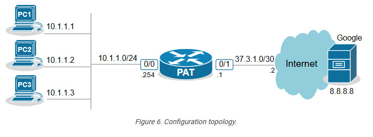
The only way to allow all hosts on the inside to communicate with the outside using one public IP is by using PAT (also called NAT Overload).
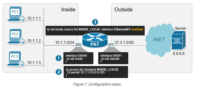
Step 1. Define Inside and Outside
The first step is always the same for every network translation type. We must tell the router which interfaces connect to the inside and which to the outside.
					interface Ethernet0/0
ip address 10.1.1.254 255.255.255.0
ip nat inside
!
interface Ethernet0/1
ip address 37.3.1.1 255.255.255.252
ip nat outside
!
We configure interface Eth0/0 as Inside and Eth0/1 as Outside.
Step 2. Define Inside Local criteria
Next, we must configure the Inside Local criteria. Basically, this tells the router which IPv4 addresses it must translate and which not. In our example, we have only one internal subnet and we configure it into an access list named INSIDE_LOCAL.
ip access-list standard INSIDE_LOCAL 10 permit 10.1.1.0 0.0.0.255
However, in real-world examples, an organization may have many inside networks, some of which must be able to pass through the router untranslated and others translated. That’s why this step exists in the process: network admins want to have complete control over which networks the router translates.
Step 3. Configure NAT rules
Lastly, we configure the PAT rule. You can see that the command has several parameters and is a bit long.
ip nat inside source list INSIDE_LOCAL interface Ethernet0/1 overload
Let’s break down and explain each parameter in the command:
- ip nat inside – The translation is for hosts physically located on the inside. Clients’ traffic will be coming to the router’s internal interface.
- source – The translation affects the source IP addresses of packets.
- list INSIDE_LOCAL – An access that contains the range of IP addresses on the inside that will be matched and translated according to the PAT rule.
- interface Ethernet0/1 – specifies the interface connected to the Outside, which IP address will be used as the public IP address for NAT translation.
- overload – This enables Port Address Translation (PAT), also known as NAT overload. When enabled, it allows multiple clients on the inside network to use a single public IPv4 address by differentiating traffic using unique port numbers for each
- connection.
Verifying PAT (NAT Overload)
Now, if we initiate some traffic from the clients to the server on the outside, we can see the active translations on the PAT router. Notice the ports used by the clients (in green) and the ports after the translation (in blue). The route has changed the entire socket (IP:port).
					NAT# sh ip nat translations
Pro Inside global Inside local Outside local Outside global
tcp 37.3.1.1:4096 10.1.1.1:40591 8.8.8.8:23 8.8.8.8:23
tcp 37.3.1.1:4097 10.1.1.2:49399 8.8.8.8:23 8.8.8.8:23
tcp 37.3.1.1:4098 10.1.1.3:61278 8.8.8.8:23 8.8.8.8:23
We can also gather some useful information using the command below.
					NAT# sh ip nat statistics
Total active translations: 3 (0 static, 3 dynamic; 3 extended)
Outside interfaces:
Ethernet0/1
Inside interfaces:
Ethernet0/0
Hits: 140 Misses: 0
CEF Translated packets: 140, CEF Punted packets: 0
Reserved port setting disabled provisioned no
Expired translations: 3
Dynamic mappings:
-- Inside Source
[Id: 1] access-list INSIDE_LOCAL interface Ethernet0/1 refcount 3
nat-limit statistics:
max entry: max allowed 0, used 0, missed 0
Key Takeaways
Port Address Translation (PAT), also known as NAT Overload, is the most widely adopted NAT method in the networking world. It is used in almost every network – home, SOHO, small, medium, or large enterprise. It is the most critical NAT topic that network engineers must understand.
Advantages of PAT (NAT Overload)
- It allows many internal clients (inside local) to share a single public IP address (inside global), conserving IPv4 addresses.
- It replaces the client’s socket (inside local IP and port) on the client side with a new socket made of an Inside Global IP and a new port number.
- Up to 65536 internal clients can share the same public IPv4 address. (There are 216 available port numbers).
- It provides an additional level of network security because hosts on the outside cannot initiate connections to hosts on the inside.
Disadvantages of PAT (NAT Overload)
- It only works for clients in client-server communications, which is not a problem for 99% of Internet communications. However, it cannot be used to host servers on the inside that must be reachable by clients on the outside. In such scenarios, it must be combined with one-to-one mapping (static NAT).
- Some protocols and applications, such as VoIP, VPNs, and Gaming, do not tolerate change in the client port in transit and may require additional configuration.
- In high-demand networks with multiple hosts and numerous simultaneous sessions, clients may experience port exhaustion – meaning the NAT router does not have more available ports to do translation with the public IPv4 address. The problem is easily solvable by adding more Inside Global addresses, but it adds expense. (public IPs cost money)
PAT Simple Overview
PAT uses exactly this logic to translate many private IPv4 addresses on the inside with one public IPv4 address on the outside. It takes advantage of the fact that 99% of internet communications are client-server and that the server socket is permanent. In client-server communications, the client initiates the connection and chooses a random port number. The server’s port number is well-known and permanent.
How does PAT work?
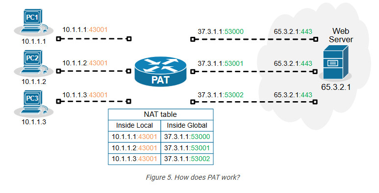
Port Address Translation (PAT), also known as NAT Overload, translates many client private addresses to one public IP address, making many TCP sessions from different clients look like many TCP sessions from one client. This does not affect the server side. However, it only works for clients in client-server communications.
For example, the three TCP sessions from PC1, PC2, and PC3 look like three TCP sessions coming from the same host, 37.3.1.1, at the server end, as shown in the diagram below.
How Does a NAT Service Work? Here’s an Example!
Let us try to understand NAT in a better way with the help of an example. Suppose that you run a company of your own and you need public IPs for your devices. But you can only get one public ID for your company, which in this example is, 150.150.0.1.
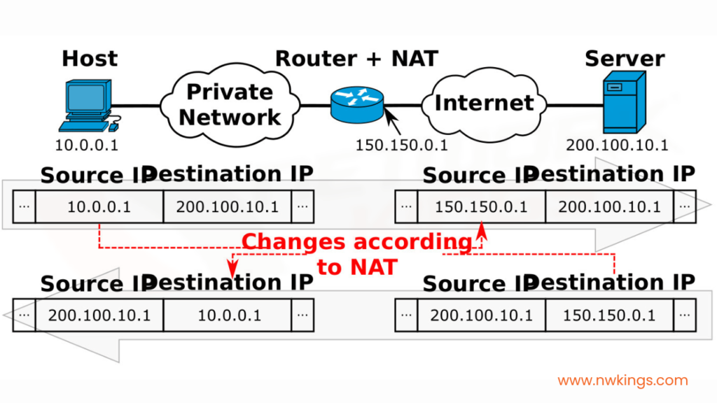
Now, there would be a private network formed along with other devices in your company. If any one host posts a request to visit, for example, facebook.com, the packet would travel from the host with a private IP address, 10.0.0.1 which will be converted by the NAT to the source public IP address of the company, 150.150.0.1. This here is the source IP address.
The destination IP address will be that of facebook.com, which is, 200.100.10.1. When the response is taken back, the source IP address becomes that of Facebook, which is 150.150.0.1, and the destination IP address becomes the public IP address of the company, which is 10.0.0.1.
All of this is recorded in a NAT Translation Table. A NAT translation table would look as such for the above example.
Inside Local IP Address | Inside Global IP Address | Outside Global IP Address |
10.0.0.1 | 150.150.0.1 | 200.100.10.1 |
<<<TRANSLATION BY NAT>>> |
You must know that the NAT Translation Table also stores the port numbers of the local IP address and global IP addresses.
Note: the server does not understand the private IP address of the source host. It only understands the public IP address presented by the NAT present in the router.
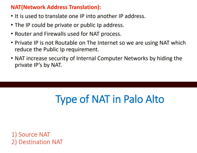
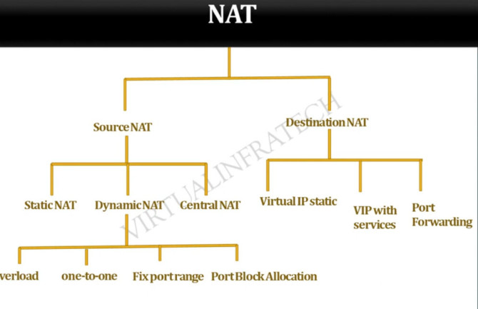
What are the Types of NAT?
There are three types of Network Address Translation. These three types are the methods by which we can configure NAT. The types are as follows:
- Static NAT
- Dynamic NAT
- NAT Overloading or Port Address Translation (PAT)
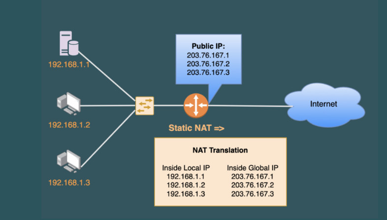
1. Static NAT:
- Static NAT is the most basic NAT.
- It is the process of one-to-one mapping one local IP address with a global IP address.
- This type of NAT configuration is not really used.
- This type of NAT serves no purpose at all because you are not able to preserve anything at all.
- This NAT is only applicable if only one person accesses the Internet at a time in a building. This is not a real-life case.
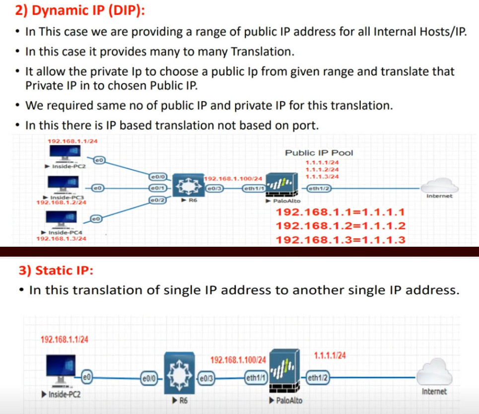
2. Dynamic NAT:
- It is a NAT configuration process in which the NAT dynamically assigns publicly registered or publicly available IP addresses to the host that sends the request in the first place to the NAT.
- The drawback of dynamic NAT is that only a fixed number of public IP addresses are available in a particular period of time.
- For example, if 20 Data Engineers work in your company for the first 5-hour shift, the request of the 21st Data engineer will be dropped!
3. NAT Overloading or Port Address Translation (PAT):
- In the NAT overloading configuration method, we further make use of the publicly reserved IP addresses for the company based on the ports.
For example, if a particular Data Engineer wants to access the Internet, the NAT will assign a specific port using a Port Address Translation (PAT) table.
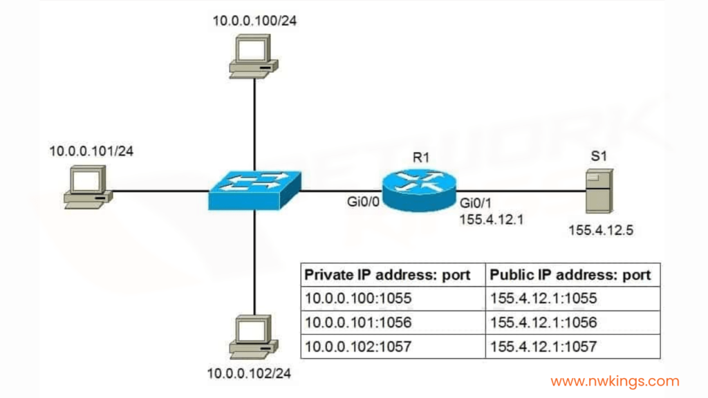
- In the PAT table, that particular request will be mapped with a specific port.
- In such a case, a particular publicly registered IP address can cater to multiple private IP addresses on multiple ports.
- This method provides us more flexibility to use publicly registered IP addresses.
NAT Slide
History of NAT (Network Address Translation)
History of NAT (Network Address Translation)
Network Address Translation (NAT) was introduced as a practical solution to the rapid exhaustion of IPv4 addresses. In the early days of the internet (1980s–early 1990s), every device connected to the network required a unique public IP address. As the internet grew quickly, it became clear that the available IPv4 address space (about 4.3 billion addresses) would not be sufficient for future expansion.
1. Early Internet and the Problem (1980s–1990s)
Initially, organizations were freely assigned public IP addresses without strict conservation policies. As more universities, companies, and users connected to the internet, the demand for IP addresses increased rapidly. This led to concerns about address depletion, which became a major issue in networking design.
2. Introduction of NAT (Mid-1990s)
To address this problem, NAT was formally introduced in 1994 through RFC 1631 titled “The IP Network Address Translator (NAT)”. This document described how private IP addresses could be translated into public IP addresses, allowing multiple devices to share a single public IP. NAT quickly became a key technology to extend the life of IPv4.
3. Growth and Adoption (Late 1990s–2000s)
As internet usage exploded with the rise of home networks, ISPs, and businesses, NAT became widely adopted. Routers and firewalls started integrating NAT as a standard feature. Technologies like PAT (Port Address Translation) allowed thousands of devices to share one public IP, making NAT essential for both enterprise and home networks.
4. NAT and Private IP Addressing
Along with NAT, private IP address ranges were defined in RFC 1918 (1996). These ranges (like 192.168.x.x, 10.x.x.x) are not routable on the internet and are used inside local networks. NAT works together with these private IPs to enable communication with external networks.
5. NAT vs IPv6 (2000s–Present)
NAT was always considered a temporary solution until the adoption of IPv6, which provides a much larger address space. However, IPv6 adoption has been slow, so NAT is still widely used today. While IPv6 eliminates the need for NAT, many networks still rely on it due to compatibility and infrastructure reasons.
6. Modern Use of NAT
Today, NAT is a standard feature in almost all routers, firewalls, and cloud environments. It is used not only for conserving IP addresses but also for basic security and network design. Variants like Carrier-Grade NAT (CGNAT) are used by ISPs to serve large numbers of customers with limited public IPs.
7. Summary
NAT emerged as a critical solution to the IPv4 address shortage in the 1990s and has remained a fundamental part of networking ever since. Even though IPv6 aims to replace the need for NAT, it continues to play a major role in modern networks due to its practicality and widespread deployment.
How NAT Works (Network Address Translation)
How NAT Works (Network Address Translation)
Network Address Translation (NAT) works by modifying IP address (and sometimes port number) information in network packets as they pass through a router or firewall. Its main role is to translate private IP addresses used inside a local network into public IP addresses used on the internet, and vice versa.
1. Basic Working Principle
When a device inside a private network wants to access the internet, it cannot use its private IP directly because private IPs are not routable on the public internet. So, the NAT-enabled router replaces the private IP address with its own public IP address before sending the packet outside.
When the response comes back, the router performs the reverse translation and forwards the packet to the correct internal device.
2. Step-by-Step NAT Process
Let’s understand with an example:
- PC IP: 192.168.1.10
- Router Public IP: 203.0.113.5
- Destination (Website): 8.8.8.8
Step 1: Packet Creation
The PC sends a request to access a website (e.g., ping or HTTP request).
Source IP = 192.168.1.10
Destination IP = 8.8.8.8
Step 2: Packet Reaches NAT Router
The router receives the packet and checks if NAT is configured. It sees that the source IP is private and needs translation.
Step 3: NAT Translation (Source NAT)
The router replaces the source IP (192.168.1.10) with its public IP (203.0.113.5).
If using PAT, it also assigns a unique port number.
Example after translation:
Source IP = 203.0.113.5:5000
Destination IP = 8.8.8.8
The router stores this mapping in a NAT table.
Step 4: Packet Sent to Internet
The modified packet is sent over the internet. To the destination server, it looks like the request came from the router’s public IP.
Step 5: Response from Server
The server (8.8.8.8) sends a response back to:
Destination IP = 203.0.113.5:5000
Step 6: Reverse Translation
The router receives the response and checks its NAT table. It finds the matching entry:
203.0.113.5:5000 → 192.168.1.10
The router replaces the destination IP with the original private IP.
Step 7: Packet Delivered to Device
The router forwards the packet to the PC (192.168.1.10), completing the communication.
3. NAT Table (Important Concept)
The NAT device maintains a table like this:
					Inside Local IP	Inside Global IP
192.168.1.10:5000	203.0.113.5:5000
This table helps the router track multiple sessions and correctly route return traffic.
4. Types of NAT Operation
- Source NAT (SNAT): Changes the source IP (used when going out to internet)
- Destination NAT (DNAT): Changes the destination IP (used for incoming traffic like port forwarding)
Example of DNAT:
Public IP (203.0.113.5:80) → Private Server (192.168.1.100:80)
5. Inside vs Outside Terms
- Inside Local: Private IP inside network (e.g., 192.168.1.10)
- Inside Global: Public IP representing inside device (e.g., 203.0.113.5)
- Outside Global: Public IP of external server (e.g., 8.8.8.8)
- Outside Local: Same as outside global (usually)
6. Real-Life Example
In a home network:
- Many devices (mobile, laptop, smart TV) have private IPs
- Router has one public IP from ISP
All devices access the internet through that single public IP using NAT. The router manages all communication using its NAT table.
7. Key Points to Remember
- NAT translates private IP ↔ public IP
- Uses a NAT table to track connections
- PAT uses port numbers to support multiple devices
- Works in both outgoing (SNAT) and incoming (DNAT) traffic
Types of NAT (Network Address Translation)
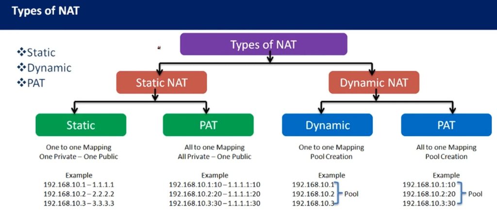
Types of NAT (Network Address Translation)
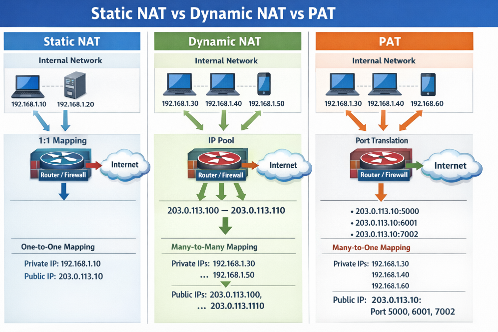
NAT is mainly divided into three major types: Static NAT, Dynamic NAT, and PAT (Port Address Translation). Each type works differently and is used based on network requirements.
1. Static NAT (One-to-One NAT)
Static NAT creates a fixed mapping between one private IP address and one public IP address. This mapping never changes, meaning the same private device always uses the same public IP.
How it works:
The router is manually configured to map a private IP to a specific public IP. Whenever traffic goes out or comes in, the same mapping is used.
Example:
- Private IP: 192.168.1.10
- Public IP: 203.0.113.10
If a server inside the network (192.168.1.10) sends traffic, it will always appear on the internet as 203.0.113.10. Similarly, external users can access the server using the public IP.
Use Case:
Used for web servers, mail servers, or any service that must be accessible from the internet.
Key Point:
- Permanent mapping
- Requires one public IP per device
2. Dynamic NAT (Many-to-Many NAT)
Dynamic NAT maps private IP addresses to a pool (group) of public IP addresses. The mapping is temporary and assigned dynamically when needed.
How it works:
When a device wants to access the internet, the router selects an available public IP from the pool and assigns it to that device. Once the session ends, the IP is returned to the pool.
Example:
- Private IPs: 192.168.1.10, 192.168.1.11
- Public IP Pool: 203.0.113.10 – 203.0.113.20
If 192.168.1.10 connects to the internet, it may get 203.0.113.10. Another device may get 203.0.113.11. If all public IPs are in use, new connections are blocked.
Use Case:
Used in organizations where limited public IPs are available but more than one public IP exists.
Key Point:
- Temporary mapping
- Needs multiple public IPs
- Limited by pool size
3. PAT (Port Address Translation) / NAT Overload
PAT is the most commonly used NAT type. It allows multiple private IP addresses to share a single public IP address by using different port numbers.
How it works:
The router changes not only the IP address but also the port number of each connection. It keeps track of all connections using a NAT table.
Example:
- Private IPs:
- 192.168.1.10 → Port 5000
- 192.168.1.11 → Port 5001
- Public IP: 203.0.113.5
When both devices access the internet:
- 192.168.1.10 → 203.0.113.5:5000
- 192.168.1.11 → 203.0.113.5:5001
The router uses port numbers to identify which response belongs to which device.
Use Case:
Used in home networks, offices, and ISPs (most common scenario).
Key Point:
- Many-to-one mapping
- Uses port numbers
- Highly efficient
4. Comparison Table
| Feature | Static NAT | Dynamic NAT | PAT (NAT Overload) |
|---|---|---|---|
| Mapping Type | One-to-One | Many-to-Many | Many-to-One |
| IP Assignment | Fixed | Dynamic | Dynamic (with ports) |
| Public IP Needed | Equal to devices | Pool required | Only one |
| Use Case | Servers | Medium networks | Home/Office |
| Efficiency | Low | Medium | High |
5. Simple Real-Life Analogy
- Static NAT: Like having your own personal phone number (fixed identity).
- Dynamic NAT: Like using any available phone from a pool when needed.
- PAT: Like many people sharing one phone number but using extensions (port numbers).
6. Summary
Static NAT is used for fixed access, Dynamic NAT is used when multiple public IPs are available, and PAT is the most efficient and widely used method that allows many devices to share a single public IP. Each type serves a specific purpose in networking design.
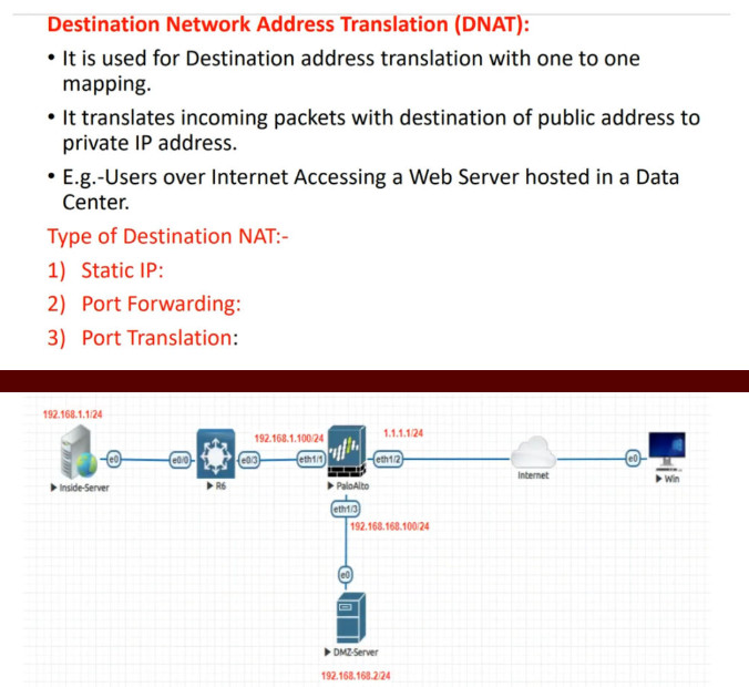
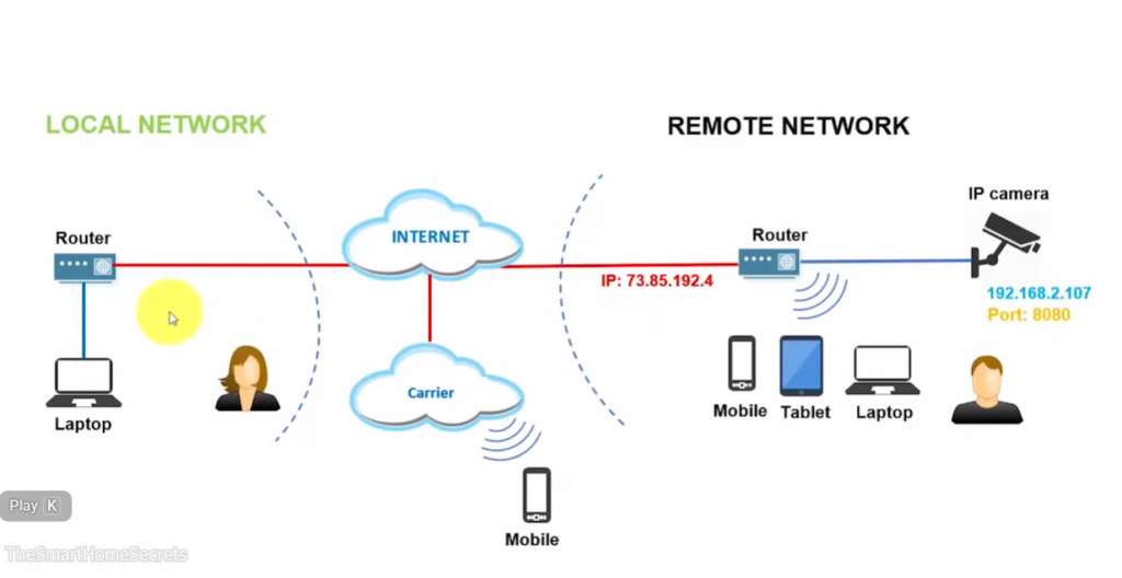
What is Port Forwarding
What is Port Forwarding
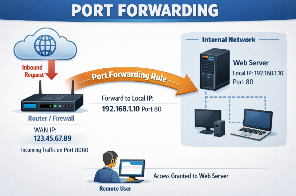
Port Forwarding is a networking technique used to allow external devices (from the internet) to access a specific device or service inside a private network. It works by mapping a public IP address and port number to a private IP address and port inside the network. Port forwarding is commonly used with NAT and is also called Destination NAT (DNAT).
1. Why Port Forwarding is Needed
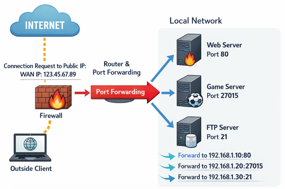
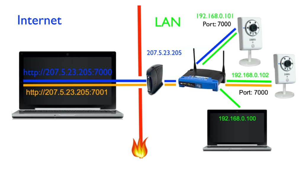
In a private network, devices use private IP addresses (like 192.168.x.x), which are not accessible directly from the internet. If you run a service inside your network (like a web server, CCTV, or game server), external users cannot reach it unless port forwarding is configured. Port forwarding solves this by directing incoming traffic to the correct internal device.
2. How Port Forwarding Works
Port forwarding works by creating a rule on the router/firewall:
- When a request comes to a specific public IP + port,
- The router forwards that request to a specific private IP + port.
This way, external users can access internal services using the router’s public IP.
3. Step-by-Step Example
Suppose:
- Router Public IP: 203.0.113.5
- Internal Web Server: 192.168.1.100
- Service Port: 80 (HTTP)
Step 1: External Request
A user on the internet enters:http://203.0.113.5
Step 2: Router Receives Request
The router gets the request on port 80.
Step 3: Port Forwarding Rule Applied
Router checks its rule:
203.0.113.5:80 → 192.168.1.100:80
Step 4: Forward to Internal Server
The router forwards the request to the internal server (192.168.1.100).
Step 5: Server Responds
The server sends a response back to the router.
Step 6: Router Sends Response to User
The router sends the response back to the external user.
4. Common Ports Used in Port Forwarding
| Service | Port Number |
|---|---|
| HTTP (Web) | 80 |
| HTTPS (Secure Web) | 443 |
| FTP | 21 |
| SSH | 22 |
| RDP (Remote Desktop) | 3389 |
6. Real-World Use Cases Port Forwarding
- Accessing CCTV cameras remotely
- Hosting a website from home/office
- Online gaming servers
- Remote desktop access to office PC
7. Advantages of Port Forwarding
- Enables remote access to internal services
- Easy to configure on most routers
- Useful for hosting applications
8. Disadvantages of Port Forwarding
- Security risk if not configured properly
- Exposes internal devices to the internet
- Can be targeted by hackers if ports are open
Static Public IP
1. What is Static Public IP?
A Static Public IP address is an IP address given by your ISP (Internet Service Provider) that:
- Does NOT change (fixed)
- Is accessible from the internet
- Is used to connect your network/device from outside
👉 Example:
Your NVR (CCTV recorder) has IP 192.168.1.100 (private)
So from outside (mobile/internet), you access:
49.204.55.10:port
2. Static vs Dynamic IP
| Feature | Static Public IP | Dynamic IP |
|---|---|---|
| IP Change | No (fixed) | Yes (changes) |
| Remote Access | Easy | Difficult |
| Use Case | CCTV, Server, VPN | Normal browsing |
| Cost | Paid | Usually free |
3. Why Static IP needed for CCTV (NVR)?
A Static Public IP is important for CCTV (NVR) because it provides a fixed and reliable address to access your cameras from anywhere over the internet. When you configure port forwarding on your router, it links your NVR’s internal (private) IP to a public IP. If the public IP keeps changing (dynamic IP), the connection will break and you won’t be able to view your CCTV remotely unless you update the IP every time. A static IP solves this problem by staying constant, ensuring uninterrupted remote monitoring, stable connectivity, and easy access through mobile apps or browsers without repeated configuration changes.
- You need a fixed IP to access camera remotely
- Without static IP, IP keeps changing → connection fails
Used for:
- CCTV remote view
- Remote Desktop
- Hosting server
- VPN
4. ISP Charges in India (Approx)
Charges depend on ISP like Airtel, Jio, BSNL, ACT, etc.
👉 Typical cost:
- ₹150 to ₹500 per month (common range)
- Some business plans include static IP free
- One-time setup fee may apply (₹500–₹2000)
5. Alternative (If no Static IP)
If static IP is expensive, you can use:
- DDNS (Dynamic DNS) → free/low cost
- Cloud-based CCTV apps (Hikvision, CP Plus, Dahua)
6. Simple Understanding
👉 Static Public IP = Permanent address of your network on internet
👉 Required for = Port forwarding + CCTV remote access
DDNS (Dynamic DNS)
What is DDNS
DDNS (Dynamic DNS) is a service that allows you to access a device or network over the internet using a fixed domain name, even when your public IP address changes frequently. Normally, internet service providers assign dynamic IPs that change over time, making remote access difficult. DDNS solves this problem by automatically updating the current IP address and linking it to a constant hostname (like a website name). This is especially useful for applications like CCTV (NVR), remote desktop, and home servers, where you need reliable remote access without purchasing a static public IP.
Why need DDNS (Dynamic DNS)
DDNS is needed when your internet connection uses a dynamic public IP address that keeps changing. Without DDNS, every time your ISP changes your IP, you must manually check the new IP and update it to access your devices remotely. This is difficult and unreliable. DDNS solves this problem by providing a fixed domain name and automatically linking it to your latest IP address, so you can always connect without worrying about IP changes.
Example (CCTV / NVR)
- Your home NVR IP today:
49.204.55.10 - Tomorrow ISP changes it to:
49.204.60.22
❌ Without DDNS:
- Old IP stops working
- You cannot access CCTV remotely
With DDNS:
- You use:
mycctv.ddns.net - DDNS updates new IP automatically
- Remote access works anytime
Simple Line
👉 DDNS is needed to provide stable remote access when IP address is changing