Manage Switch Features
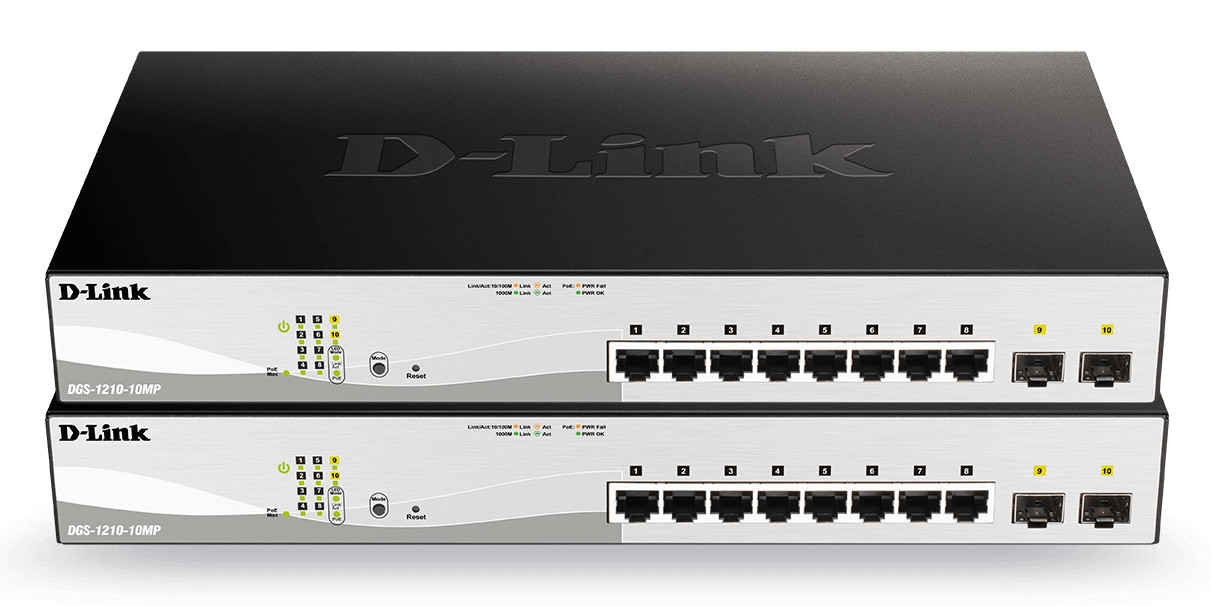
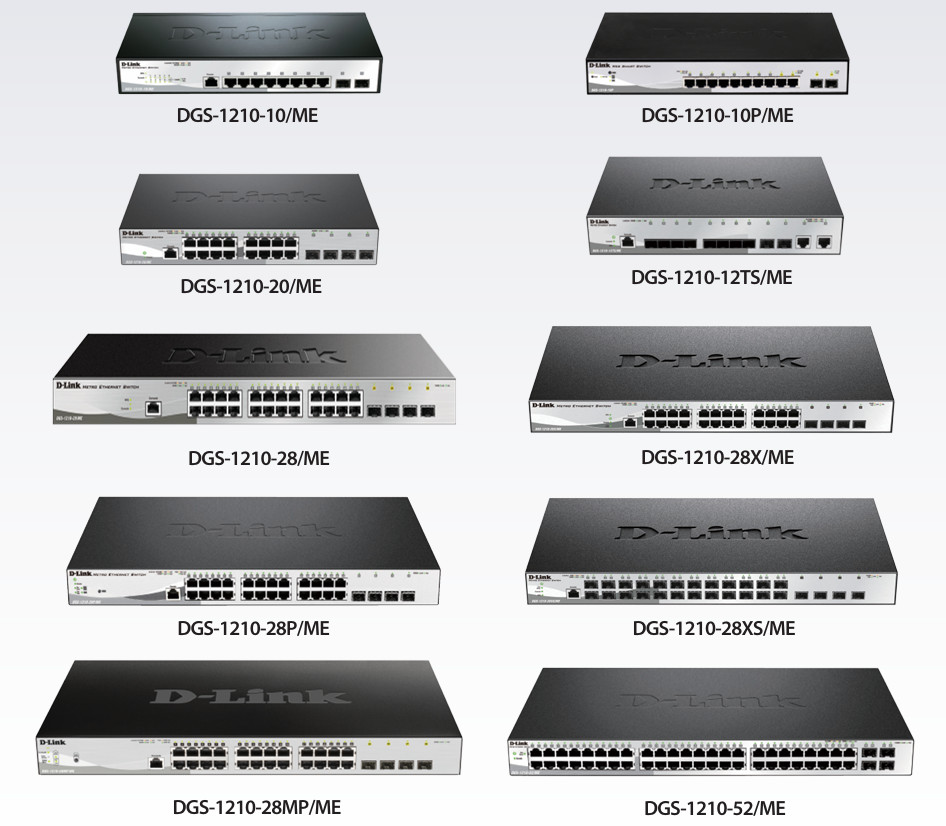
L2 Smart Managed Switches
Security
- Access Control List
- D-Link Safeguard Engine
- Port Security
- ARP Spoofing Prevention
- Smart IP-MAC-Port Binding
- DHCP Server Screening
Management
- IPv4/ IPv6 Dual Stack
- Web GUI (supports 10 languages)
- SmartConsole utility
- SNMP and RMON
- Simplified CLI through Telnet
QoS
- Supports IEEE 802.1p QoS
- Supports DSCP
Advanced Features
- Auto Surveillance VLAN
- Auto Voice VLAN
- Port or VLAN-based Loopback Detection
- Cable Diagnostics
- LLDP/LLDP-MED
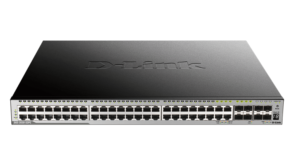
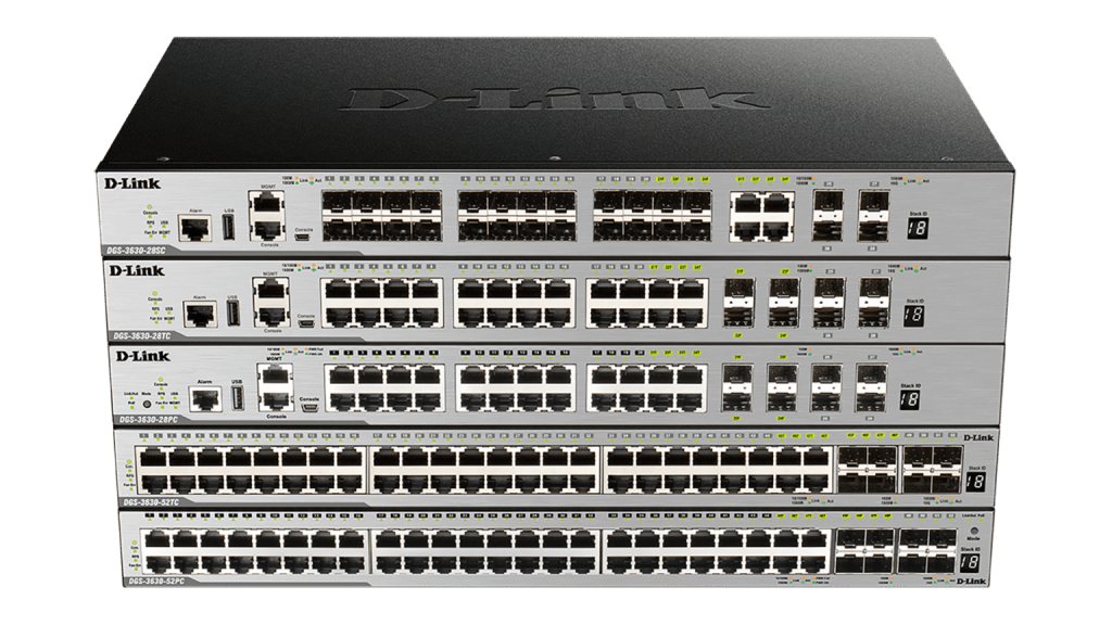
L3 Stackable Managed Switches
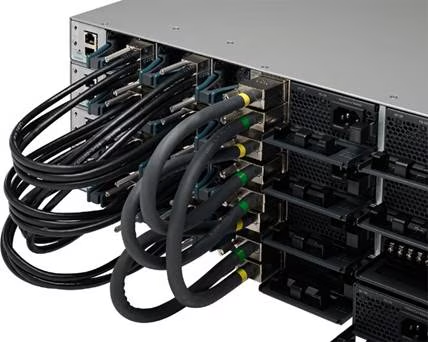
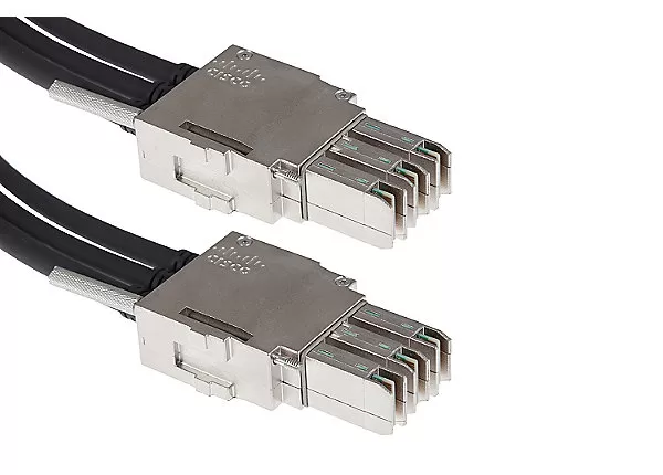
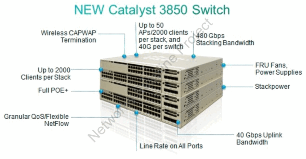
Cisco 3850 Series PoE+ 48 Port Switch
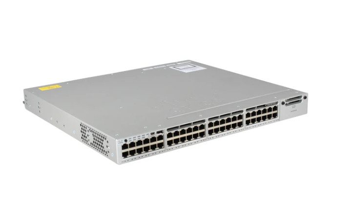
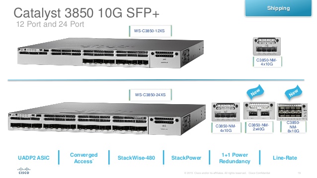
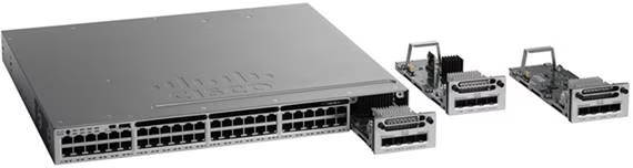
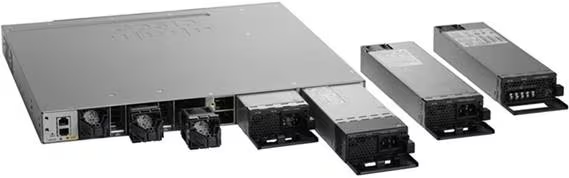
Standard Features:
- Flexible NetFlow (FNF)
- Control and Provisioning of Wireless Access Points (CAPWAP)
- Dynamic Host Configuration Protocol (DHCP)
- Stacking Master Configuration Management
- Cisco StackWise-480
- Autonegotiation
- Dynamic Trunking Protocol (DTP)
- Port Aggeration Protocol (PAgP)
- Link Aggeration Protocol (LACP)
- Automatic Media-Department Interface Crossover (MDIX)
- Switching Database Manager (SDM)
- Local Proxy Address Resolution Protocol (ARP)
- Unidirectional Link Detection Protocol (UDLD)
- Smart Multicast, With Cisco FlexStack-Plus Technology
- Internet Group Management Protocol (IGMP)
- Voice VLAN
- Cisco VLAN Trunking Protocol (VTP)
- Layer 2 Trace Route
- Trivial File Transfer Protocol (TFTP)
- Network Timing Protocol (NTP)
- Private VLANs
- Access Control Lists (ACL’s)
- Secure Shell (SSH) Protocol
- MAC Address Notification
- Bridge Protocol Data Unit (BPDU)
- IGMP Filtering
- Cross-Stack EtherChannel
- Flexlink
- Power Redundancy
- Qos
What Features Does a Managed Switch Have?
A managed switch is an advanced network switch that gives full control over how traffic moves in a network. Unlike an unmanaged switch, it can be configured, monitored, and controlled using a web interface, CLI, or network management tools. It is commonly used in offices, enterprises, and data centers where network control and security are important.
VLAN Support
One of the main features of a managed switch is VLAN support. VLANs allow a network to be divided into multiple logical networks even if all devices are physically connected to the same switch. This improves security and reduces unnecessary broadcast traffic. For example, HR, IT, and Finance departments can be separated into different VLANs.
Quality of Service (QoS)
Another important feature is Quality of Service (QoS). QoS allows prioritization of network traffic based on importance. For example, voice calls (VoIP) and video conferencing can be given higher priority compared to normal file downloads, ensuring smooth communication without delays or interruptions.
Port Security
Managed switches also support Port Security, which allows administrators to control which devices can connect to specific ports. This helps prevent unauthorized access and improves network security by limiting unknown devices from joining the network.
Spanning Tree Protocol (STP)
They also provide Spanning Tree Protocol (STP) support, which prevents network loops when multiple switches are connected. STP automatically blocks redundant paths and ensures there is only one active path between devices, improving network stability and preventing broadcast storms.
Monitoring and Troubleshooting Tools
Another key feature is monitoring and troubleshooting tools, such as port mirroring and SNMP (Simple Network Management Protocol). These features allow network administrators to monitor traffic, detect issues, and analyze network performance in real time.
Link aggregation (LACP)
Managed switches also support link aggregation (LACP), which combines multiple physical links into one logical link. This increases bandwidth and provides redundancy, so if one link fails, traffic continues through the remaining links without interruption.
Remote Management Capability
A managed switch provides remote management capability, which allows network administrators to configure and control the switch from anywhere using a web interface, CLI (Command Line Interface), or network management software. This makes it easier to manage large networks without physically accessing the device.
SNMP (Simple Network Management Protocol)
It also supports SNMP (Simple Network Management Protocol), which helps in monitoring network performance in real time. With SNMP, administrators can track traffic usage, detect faults, and receive alerts when there are network issues.
Port Mirroring
Another important feature is port mirroring, which copies traffic from one port to another for monitoring and troubleshooting. This is useful for analyzing network problems or detecting suspicious activity using network analyzers.
Firmware upgrade and backup configuration options
They also provide firmware upgrade and backup configuration options, allowing administrators to update the switch software for new features or security patches. Backup configurations ensure that settings can be restored quickly in case of failure.
Access control lists (ACLs)
Managed switches also include access control lists (ACLs), which help filter traffic based on rules such as IP address, MAC address, or protocol type. This improves network security by allowing or blocking specific types of traffic.
- VLAN Support – divides a network into multiple logical networks for security and efficiency.
- QoS (Quality of Service) – prioritizes important traffic like voice and video over normal data.
- Remote management – allows configuration via web interface, CLI, or SNMP.
- Port Security – restricts unauthorized devices from accessing specific switch ports.
- STP/RSTP – prevents network loops and ensures stable switching paths.
- Link Aggregation (LACP) – combines multiple links to increase speed and provide redundancy.
- Port Mirroring – copies traffic to another port for monitoring and troubleshooting.
- ACL (Access Control List) – filters traffic based on IP, MAC address, or protocols.
- PoE (Power over Ethernet) – supplies power and data through the same cable.
- Traffic Monitoring – tracks network usage and helps detect performance issues.
- Firmware Upgrade – allows software updates for new features and security fixes.
- Bandwidth Control – limits or manages traffic usage per port or user.
- SNMP Monitoring – collects network performance data and sends alerts for issues.
- DHCP Snooping – blocks fake DHCP servers and improves network security.
- Storm Control – prevents broadcast, multicast, and unknown traffic storms.
- MAC Address Filtering – allows or blocks devices based on MAC addresses.
- Spanning Tree enhancement (PVST/MSTP) – improves loop prevention in large networks.
- IPv6 Support – enables modern network addressing and communication.
- Stacking Support – combines multiple switches into one logical managed unit.
- Access Port Configuration – assigns specific VLANs and policies to individual ports.
- Energy efficiency (EEE) – reduces power consumption when traffic is low.
- Logging & Event Tracking – records network activities for troubleshooting and audits.
Switch Security Features
- Port Security – restricts which devices can connect to a switch port using MAC address control.
- MAC Address Filtering – allows or blocks traffic based on specific MAC addresses.
- DHCP Snooping – prevents fake DHCP servers from assigning incorrect IP addresses.
- Dynamic ARP Inspection (DAI) – stops ARP spoofing and protects against man-in-the-middle attacks.
- Access Control List (ACL) – filters network traffic based on IP, protocol, or port rules.
- 802.1X Authentication – ensures only authorized users/devices can access the network.
- Storm Control – blocks excessive broadcast, multicast, or unknown traffic to prevent network flooding.
- Private VLANs (PVLAN) – isolates devices within the same VLAN for extra security.
- IP Source Guard – blocks IP spoofing by validating IP-to-MAC bindings.
- Secure Management Access (SSH/HTTPS) – encrypts switch management access to prevent hacking.
- BPDU Guard – protects STP by disabling ports if unauthorized switches are connected.
- Root Guard – prevents unauthorized devices from becoming STP root bridge.
What is Auto-MDIX in Switch?
Auto-MDIX (Automatic Medium-Dependent Interface Crossover) is a switch feature that automatically detects the type of Ethernet cable connected (straight-through or crossover) and adjusts the port accordingly.
In simple terms, it removes the need to worry about using the correct cable type. If two similar devices are connected (like switch-to-switch or PC-to-PC), the switch automatically fixes the transmit and receive signal paths inside the port so communication works properly.
For Example, without Auto-MDIX, you would need a Crossover Cable for switch-to-switch connections and a Straight-Through Cable for PC-to-switch connections. With Auto-MDIX enabled, any standard Ethernet cable can be used, and the switch will automatically configure itself.
This feature reduces cabling errors, simplifies network setup, and improves flexibility in managing LAN connections.
In conclusion, a managed switch provides advanced features like VLANs, QoS, security controls, STP, monitoring, and link aggregation. These features make it essential for modern enterprise networks where performance, security, and control are required.
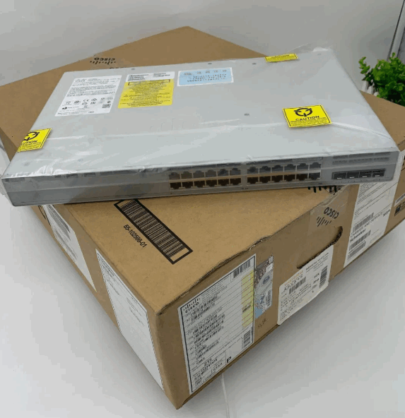
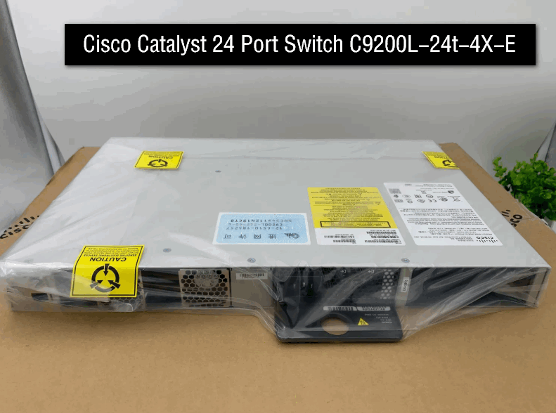
Cisco Catalyst 9200 series in India, current online prices vary significantly by exact model and license.
Approximate current prices
- C9200 / 24-port data: around ₹75,000–₹1.05 lakh depending on configuration.
- C9200L-24T-4G-E — 24 data ports + 4×1G uplinks: roughly ₹67,000+ in some listings.
- C9200L-24P-4G — 24-port PoE+ + 4×1G uplinks: roughly ₹1.8–2.5 lakh in current Indian listings.
- C9200L-48T-4X — 48 data ports + 4×10G uplinks: around ₹95,000+ in some listings.
Cisco’s own specifications confirm that the 9200L family includes 24/48-port models with 1G and 10G uplink options, as well as PoE+ variants.
For your networking lab, if you don’t need PoE, I’d look specifically at C9200L-24T-4G-E or C9200L-24T-4X-E. You get a proper enterprise Layer-3 Cisco switch without spending the extra money on PoE.
If you want, I can also compare C9200L vs C9300 vs MikroTik CRS326 for your lab and tell you which gives the best value.
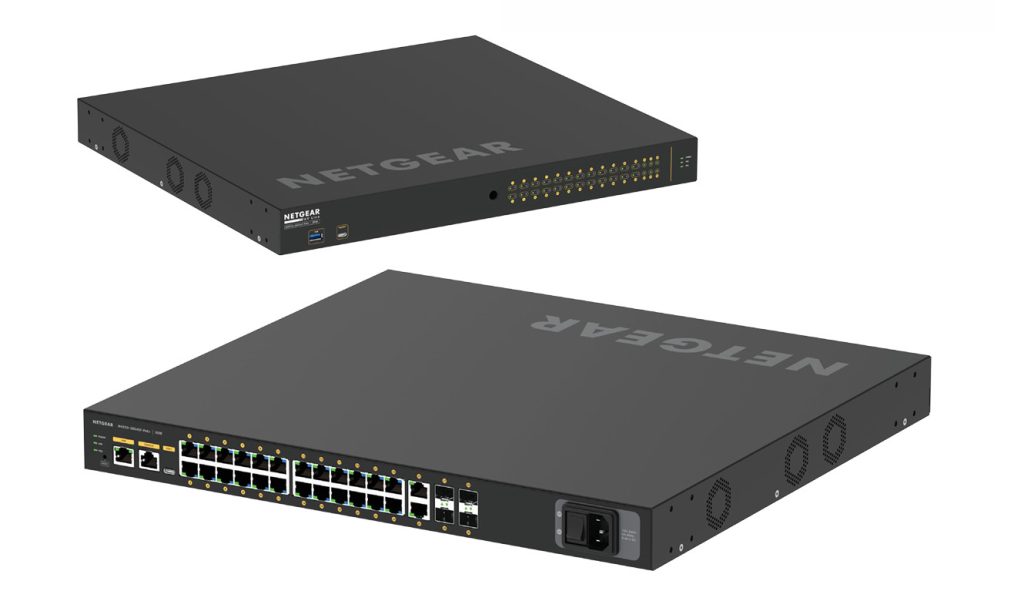
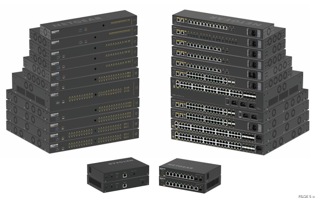
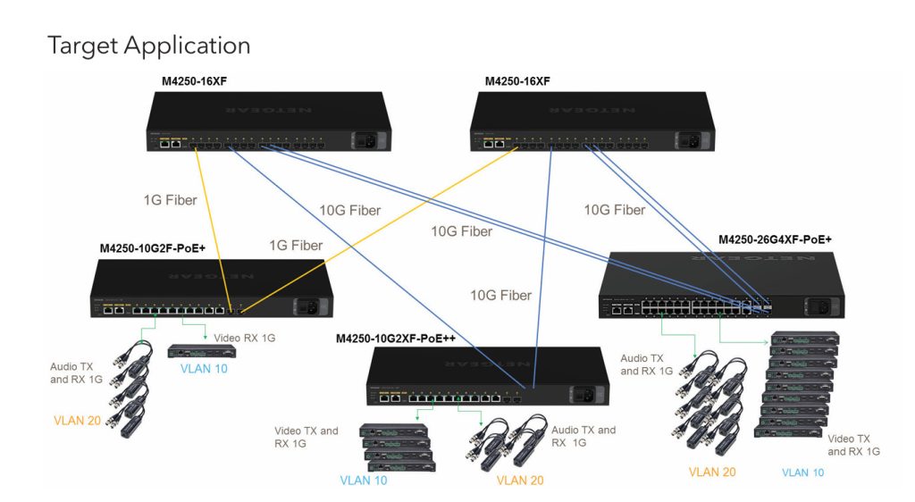
AV Over IP Managed Switches

What is AV over IP Short Explain?
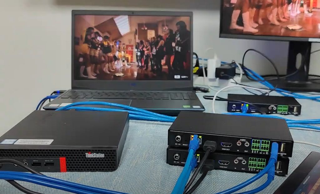
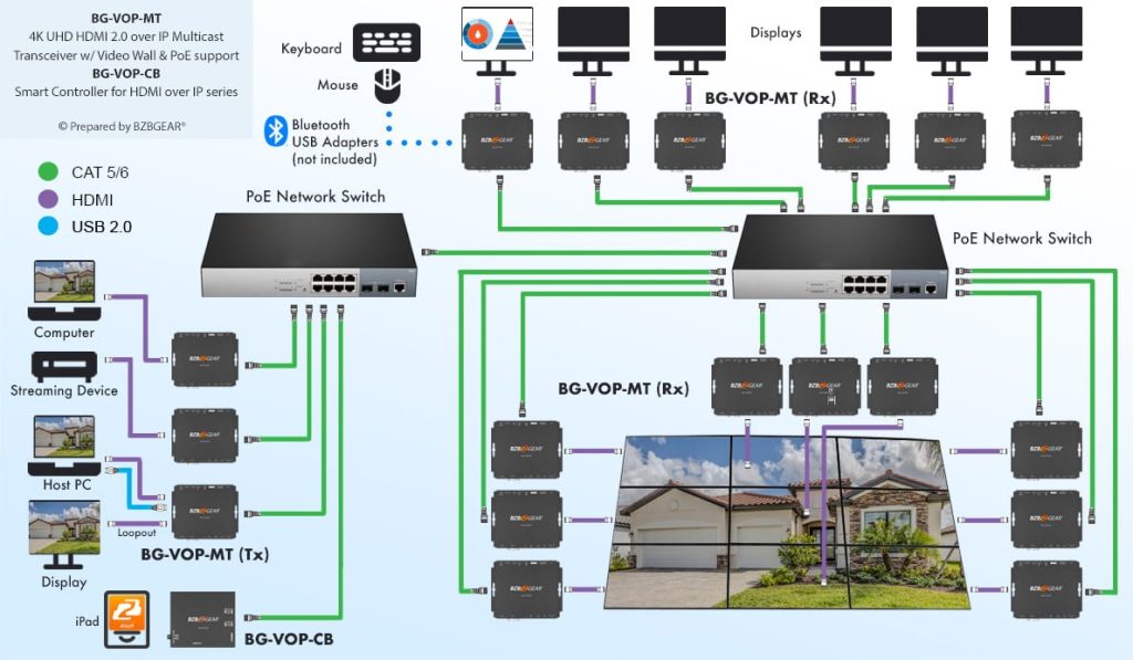
AV over IP (Audio-Visual over Internet Protocol) is a technology used to transmit audio and video signals over an IP/Ethernet network instead of using traditional point-to-point AV cables.
Key Points
- AV = Audio + Video — It carries both audio and video signals.
- IP = Internet Protocol — AV data is transported using standard IP networking technology.
- Encoder — Converts HDMI/audio signals into an IP-based network stream.
- Network Switch — Transports the AV stream through Ethernet infrastructure.
- Decoder — Converts the IP stream back into HDMI/audio for the display.
- Ethernet Network — Cat6/Cat6A, fiber, 1G/10G or higher networks can be used depending on the system.
- Multicast — Allows one AV source to be distributed efficiently to multiple displays.
- IGMP Snooping — Helps control multicast traffic within the network.
- VLAN — Can be used to separate AV traffic from normal office, CCTV, or guest traffic.
- Scalable — Additional displays or sources can be added without completely redesigning the AV cabling.
- Centralized Control — Sources can often be routed to different displays through software/control systems.
- Low Latency — Professional AV-over-IP systems are designed to deliver video with very low delay.
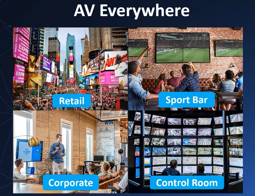
- Applications — Common in NOC rooms, conference rooms, hotels, classrooms, digital signage, control rooms, and video walls.
1. What is AV over IP?
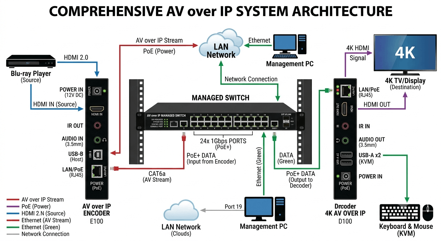
AV over IP stands for Audio-Visual over Internet Protocol. It is a technology used to transmit audio and video signals through an IP-based Ethernet network. In a traditional AV system, a video source such as a computer, camera, set-top box, or media player is normally connected directly to a display using HDMI, DisplayPort, SDI, or another dedicated cable. In an AV-over-IP system, the audio and video signal is first converted into a network stream by an AV Encoder. The stream is then transported through an Ethernet/IP network using network switches. At the destination, an AV Decoder receives the stream, decodes it, and converts it back into an HDMI or other display-compatible signal. The basic concept can therefore be remembered as Source → Encoder → IP Network → Decoder → Display.
2. Why is AV over IP needed?
AV over IP is mainly used when the number of video sources and displays becomes large or when the devices are located at different locations. Suppose an organization has 10 computers, 5 CCTV/NVR sources, and 20 television displays. Connecting every source to every display using traditional HDMI cables can become complicated, expensive, and difficult to manage. AV over IP solves this problem by using an Ethernet network as the distribution infrastructure. Once the encoders, decoders, and network switches are installed, sources can be routed to different displays through software or a centralized controller. This makes the system much more scalable and flexible than a traditional point-to-point AV installation.
3. Basic AV over IP Architecture
The basic architecture of an AV-over-IP system is:
					Video Source
     │
     │ HDMI
     ▼
AV Encoder
     │
     │ Ethernet
     ▼
Managed Network Switch
     │
     │ IP Network
     ▼
AV Decoder
     │
     │ HDMI
     ▼
TV / Projector / LED Display
The source generates the original audio/video signal. The encoder converts that signal into an IP-based stream. The network switch transports the stream across the network. The decoder receives and decodes the stream and produces a normal AV output. Finally, the display shows the video and plays the audio. In a large installation, there may be hundreds of encoders and decoders connected to multiple network switches.
4. What is an AV Encoder?
An AV Encoder is a hardware device that converts an audio/video signal into a format suitable for transmission over an IP network. For example, a laptop may have an HDMI output. That HDMI output can be connected to the HDMI input of an AV encoder. The encoder captures the video and audio, processes it according to the particular AV-over-IP technology, and sends the resulting network stream through its Ethernet port. Depending on the system, the encoder may perform video compression, packetization, buffering, encryption, and other processing. Professional encoders are designed to maintain high video quality while keeping latency and bandwidth within acceptable limits.
5. What is an AV Decoder?
An AV Decoder performs the reverse operation of an encoder. It receives the AV stream from the IP network and converts it back into a display-compatible signal. For example, a decoder may receive a video stream through its Ethernet port and provide an HDMI output to a television. The decoder may also provide audio output depending on the equipment. In a large AV installation, every display does not necessarily need a direct HDMI connection to the source. Instead, the display can have a decoder connected through the network. This is one of the main reasons AV over IP is highly scalable.
6. AV over IP does not necessarily mean the public Internet
The word IP in AV over IP does not mean that the video has to travel through the public Internet. In most professional installations, AV traffic can remain completely inside a private LAN. For example:
					PC
 │
Encoder
 │
Ethernet
 │
Switch
 │
Ethernet
 │
Decoder
 │
TV
The Internet can be disconnected and the local AV system may continue working because the communication is taking place inside the local Ethernet network. This is particularly useful in hotels, hospitals, offices, NOCs, control rooms, and other environments where local video distribution must continue even if the Internet connection fails.
7. Unicast in AV over IP
Unicast is a one-to-one communication method. In an AV-over-IP environment, one encoder can send a stream specifically to one decoder. For example, if a computer is connected to Encoder-01 and TV-01 is connected to Decoder-01, the encoder can send its video stream directly to that decoder. Unicast is simple and can work well when a source is required at only one destination. However, if the same source needs to be displayed on many screens, sending a separate stream to every decoder can consume significant network bandwidth.
8. Multicast in AV over IP
Multicast is one of the most important concepts in professional AV over IP. With multicast, a source can transmit a single stream into the network, and multiple receivers can subscribe to that stream. For example, suppose one NVR needs to be displayed on 20 TVs. Instead of sending 20 separate copies of the video stream, the encoder can generate one multicast stream. The required decoders join the appropriate multicast group and receive the stream. This makes multicast very efficient for large-scale AV distribution. However, multicast must be properly configured on the network; otherwise, unnecessary multicast traffic can flood network ports and consume bandwidth.
9. What is IGMP Snooping?
IGMP Snooping is a feature available on managed Ethernet switches that helps control multicast traffic. The switch monitors IGMP messages and learns which ports are interested in particular multicast groups. It can then forward multicast traffic only to the ports that actually need it. This is extremely important in AV-over-IP networks because video streams can consume large amounts of bandwidth. Without proper IGMP configuration, multicast traffic may be flooded across many switch ports, potentially causing network congestion and affecting other services.
10. What is an IGMP Querier?
An IGMP Querier helps maintain multicast group membership information. It periodically sends queries to devices on the network to determine which receivers are still interested in particular multicast groups. The receivers respond with their membership information. This allows the network to maintain an accurate picture of which devices need which multicast streams. In a properly designed AV-over-IP network, IGMP Snooping and IGMP Querier configuration should be considered carefully, especially when multiple switches and VLANs are involved.
11. VLAN in AV over IP
VLAN (Virtual Local Area Network) can be used to logically separate AV traffic from other network traffic. For example, a company may have:
					VLAN 10 → Office Users
VLAN 20 → CCTV
VLAN 30 → AV over IP
VLAN 40 → Network Management
The AV endpoints can be placed in a dedicated AV VLAN. This can improve traffic management, troubleshooting, and security. VLANs are especially useful in enterprise environments where the same physical network infrastructure carries multiple types of traffic. When multicast is involved, VLAN design becomes even more important because multicast traffic should be carefully controlled.
12. QoS in AV over IP
QoS means Quality of Service. It is a network mechanism used to prioritize important traffic. In an enterprise network, AV traffic may compete with file transfers, Internet traffic, backups, voice calls, and other applications. If the network becomes congested, video may experience packet loss, freezing, or increased latency. QoS can help prioritize latency-sensitive traffic. However, QoS does not magically create additional bandwidth. The network must still have sufficient capacity for the expected AV traffic. QoS should therefore be considered part of an overall network design rather than a replacement for proper bandwidth planning.
13. Bandwidth Requirements
Bandwidth is one of the most important considerations when designing an AV-over-IP network. The required bandwidth depends on factors such as resolution, frame rate, compression, color depth, codec, number of streams, and transmission technology. A compressed 1080p video stream may require relatively modest bandwidth, while an uncompressed 4K signal can require extremely high bandwidth. Therefore, an engineer must calculate the expected traffic before selecting switches and uplinks. It is also important to consider aggregate traffic because multiple encoders may transmit simultaneously through the same switch or uplink.
14. 1GbE and 10GbE Networks
Many compressed AV-over-IP systems can operate over 1 Gigabit Ethernet, depending on the manufacturer’s specifications and stream requirements. However, high-bandwidth systems may require 10GbE or higher-speed links, particularly for switch uplinks and core network connections. For example, if several encoders are transmitting high-bandwidth video through an access switch, a 1Gbps uplink could become a bottleneck. A professional design therefore considers both the speed of individual endpoint ports and the total capacity of the network’s aggregation and core links.
15. Video Compression
Video compression is used to reduce the amount of data required to transmit video. Raw video contains an enormous amount of data, so transmitting it without compression can require very high bandwidth. An encoder can compress the video before sending it across the network. The decoder then decompresses or decodes the stream before displaying it. Compression reduces bandwidth requirements, but it can introduce processing overhead, latency, and potentially some loss of image quality. The exact behavior depends on the codec and AV-over-IP technology being used.
16. Latency
Latency refers to the time delay between the source and the display. Imagine moving the mouse on a computer while viewing the computer screen through an AV-over-IP system. If the system has high latency, you may notice that the display reacts slightly after the actual mouse movement. For digital signage, a small amount of latency may not matter. However, low latency becomes much more important for live presentations, interactive applications, gaming, live production, and professional control rooms. When selecting AV equipment, engineers should therefore consider both video quality and latency.
17. Video Resolution
AV-over-IP systems can support different resolutions depending on the encoder, decoder, network, and technology. Common resolutions include 720p, 1080p, and 4K UHD. Higher resolution generally requires greater processing capability and potentially greater network bandwidth. Frame rate also affects bandwidth and performance. Therefore, when designing a 4K AV-over-IP system, you should verify that the source, encoder, switch, network uplink, decoder, and display all support the required resolution and frame rate.
18. PoE in AV over IP
Some AV-over-IP encoders and decoders support Power over Ethernet (PoE). With PoE, the Ethernet cable can provide both network connectivity and electrical power. Instead of connecting a decoder to both an Ethernet cable and a separate power adapter, you can connect it to a PoE-enabled switch using a suitable Ethernet cable. This can simplify installation, especially for devices mounted behind displays, in ceilings, or in locations where electrical outlets are inconvenient.
19. Cat6 and Ethernet Cabling
AV-over-IP systems commonly use structured Ethernet cabling such as Cat5e, Cat6, or Cat6A, depending on the required network speed and installation standards. Cat6 and Cat6A are often preferred for new professional installations because they provide good support for higher-speed Ethernet and future expansion. Cable length, termination quality, patch panels, connectors, and electromagnetic interference should also be considered. A poor-quality cable installation can cause packet errors and intermittent AV problems even when the encoder and decoder are functioning correctly.
20. Video Wall Applications
AV over IP can also be used to build sophisticated video walls. For example, four displays can be arranged in a 2×2 configuration:
					┌──────────┬──────────┐
│ Display1 │ Display2 │
├──────────┼──────────┤
│ Display3 │ Display4 │
└──────────┴──────────┘
A video-wall controller can divide one large source across multiple displays, allowing the four screens to act as one large visual canvas. Alternatively, each display can show a different source. This type of architecture is commonly used in NOCs, security control rooms, command centers, broadcast environments, and large corporate monitoring rooms.
21. AV over IP in Hotels
Hotels are another major application area. A hotel may have hundreds of televisions, IPTV services, digital signage displays, conference rooms, CCTV systems, and centralized media sources. AV over IP can provide a scalable infrastructure for distributing these sources. A central system can distribute promotional content, conference presentations, security video, television channels, and other media to different locations. The network can be designed using VLANs, multicast, IGMP, QoS, and redundant uplinks to provide reliable service.
22. AV over IP in Corporate Offices
In corporate offices, AV over IP can connect meeting rooms, conference rooms, presentation systems, video conferencing systems, and digital signage. A presentation computer in one room could potentially be routed to a display in another room without installing a dedicated long HDMI cable. Centralized management can also allow IT or AV administrators to monitor endpoint status and change routing remotely. This makes AV over IP particularly useful in modern enterprise buildings where flexible meeting and collaboration spaces are required.
23. Network Security
Because AV over IP uses an IP network, security should not be ignored. AV endpoints may have web-based management interfaces, usernames, passwords, APIs, and control systems. Devices should use strong credentials and appropriate firmware updates. Management traffic can be placed in a separate management VLAN, while AV traffic can be placed in an AV VLAN. Network ACLs and firewall rules can be used where appropriate to prevent unauthorized access. In an enterprise environment, AV systems should be treated as network devices rather than simply as television equipment.
24. Troubleshooting an AV-over-IP System
Troubleshooting an AV-over-IP system requires both AV knowledge and networking knowledge. If there is no video on the display, you can first check the HDMI source and encoder input. Then check whether the Ethernet link is active and whether the encoder and decoder have valid IP addresses. Next, check VLAN configuration, switch port configuration, multicast settings, IGMP Snooping, and IGMP Querier. If the stream is available but the picture freezes, investigate bandwidth utilization, packet loss, interface errors, latency, and congestion. This is why AV over IP is a particularly interesting technology for network engineers: many AV problems can actually be diagnosed using standard networking tools and concepts.
25. Advantages of AV over IP
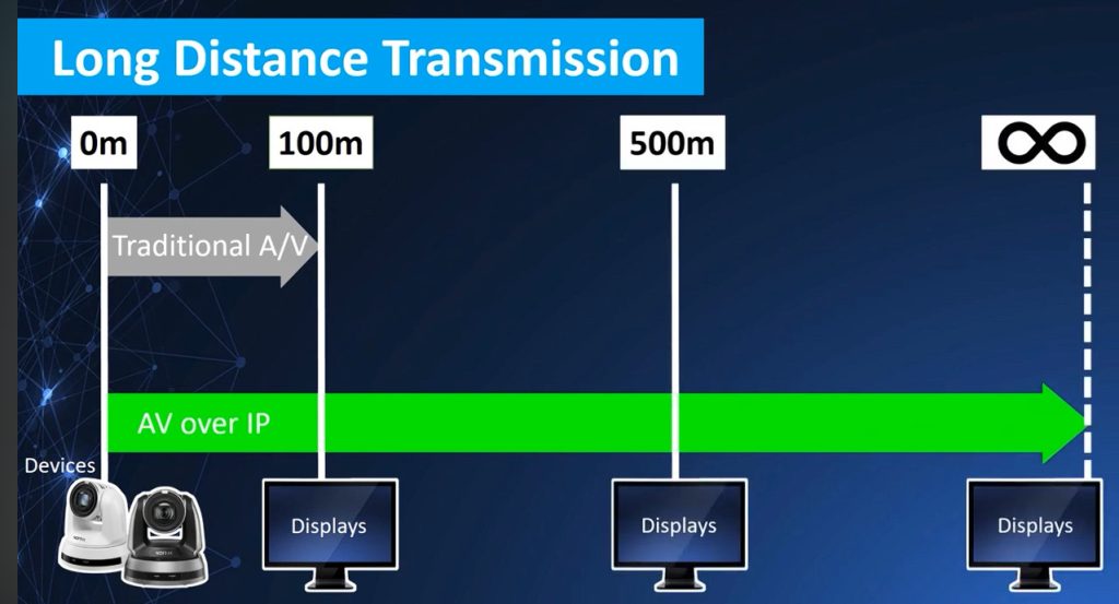
The main advantages of AV over IP are scalability, flexibility, centralized management, long-distance transmission, and efficient distribution. New displays can often be added simply by installing additional decoders and connecting them to the network. Sources can be routed to different displays without changing physical HDMI connections. Fiber can be used for long-distance connections, and existing structured cabling can often be leveraged. Centralized software can provide monitoring and control of many endpoints. These capabilities make AV over IP suitable for large and complex AV environments.
26. Disadvantages of AV over IP
AV over IP also introduces additional complexity. Unlike a simple HDMI cable, an AV-over-IP system depends on network configuration. Problems with VLANs, multicast, IGMP, bandwidth, QoS, routing, or switch configuration can affect video transmission. Hardware from different manufacturers may not always be interoperable because some systems use proprietary protocols. High-quality low-latency equipment can also be expensive. Therefore, a professional AV-over-IP installation requires careful planning of both the AV system and the network infrastructure.
real AV over IP example
1. Real-World AV over IP Example
A good real-world example of AV over IP is a hotel, corporate office, university, hospital, or NOC where multiple video sources need to be displayed on multiple screens. Instead of running long HDMI cables from every source to every display, the organization uses the existing Ethernet/IP network to transport audio and video signals. For example, a hotel may have a DTH receiver, CCTV NVR, conference-room laptop, digital-signage server, and multiple TVs. These sources can be connected to AV-over-IP encoders, while AV-over-IP decoders are connected near the TVs or projectors.
2. Video Source
The first part of the system is the video source. A source is any device that generates audio or video. In a real hotel installation, the sources could be a DTH receiver, Blu-ray player, laptop, CCTV NVR, media server, conference camera, or digital-signage computer. For example, suppose a DTH receiver produces an HDMI output. Normally, that HDMI output would have to be connected directly to a TV or an HDMI distribution system. In AV over IP, the HDMI signal is instead sent to an encoder.
3. AV Encoder
The AV encoder is responsible for taking the HDMI/audio signal and converting it into an IP-based stream that can travel through an Ethernet network. For example, the DTH receiver may be connected to the HDMI input of an encoder. The encoder then sends the video stream through its Ethernet port to the network switch. The basic concept is:
					DTH Receiver
     ↓
   HDMI
     ↓
AV Encoder
     ↓
 Ethernet
     ↓
Network Switch
The encoder is therefore the device that puts the AV content onto the IP network.
4. Managed Network Switch
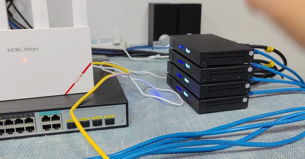
The next important component is the managed Ethernet switch. The encoder connects to the switch using Cat6/Cat6A Ethernet cable or sometimes fiber. The switch transports the AV traffic to the required decoder. In a professional installation, the switch should support the networking features required by the AV system, particularly VLANs and multicast features such as IGMP Snooping. Depending on the system and bandwidth requirements, the network may use 1GbE, 10GbE, or higher-speed links.
5. AV Decoder
At the destination side, an AV decoder receives the IP video stream from the Ethernet network and converts it back into a format that can be connected to a display, commonly HDMI. For example, the decoder may be installed behind a TV. The connection would be:
					Network Switch
      ↓
    Cat6
      ↓
  AV Decoder
      ↓
    HDMI
      ↓
      TV
Therefore, the decoder performs almost the reverse operation of the encoder.
6. Complete Real-World Connection
Putting everything together, a basic hotel AV-over-IP system could look like this:r
					DTH Receiver
     ↓ HDMI
AV Encoder
     ↓ Ethernet
Managed Switch
     ↓ Ethernet
AV Decoder
     ↓ HDMI
TV
The important difference from a traditional HDMI system is that the middle section is an IP/Ethernet network. The source and display do not need to be physically connected by a long HDMI cable.
7. One Source to Multiple Displays
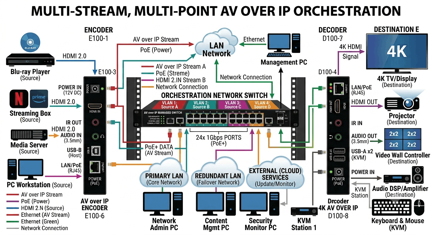
One of the major advantages of AV over IP is that a single source can be distributed to multiple displays. Suppose a hotel has one DTH receiver and wants the same channel on ten TVs. The DTH receiver connects to one encoder, and multiple decoders can receive that stream.
					                 ┌── Decoder → TV 1
                 │
                 ├── Decoder → TV 2
DTH → Encoder ───┼── Decoder → TV 3
                 │
                 ├── Decoder → TV 4
                 │
                 └── Decoder → TV 10
This makes the system much more scalable than running individual HDMI cables everywhere.
8. Multicast
For professional AV-over-IP systems, multicast is often important when one video stream needs to reach many receivers. Instead of creating a completely separate stream for every TV, the encoder can send one multicast stream and the required decoders can join that multicast group. This is particularly useful when many displays need the same content.
For example:
					Encoder
   ↓
Multicast Stream
   ↓
Managed Switch
   ├── TV 1
   ├── TV 2
   ├── TV 3
   └── TV 4
This is one reason AV-over-IP network design requires networking knowledge.
9. IGMP Snooping
IGMP Snooping is commonly used on switches in multicast AV networks. It allows the switch to learn which ports are interested in particular multicast streams. Suppose only TV 1 and TV 2 need a particular video channel. With appropriate multicast configuration, the switch can avoid unnecessarily forwarding that multicast traffic to unrelated ports.
Conceptually:
					Multicast Source
      ↓
Managed Switch
   ┌──┴────┐
   ↓       ↓
 TV 1     TV 2

TV 3 → does not need this stream
Without proper multicast handling, excessive multicast traffic can cause unnecessary network utilization.
10. IGMP Querier
In a multicast network, an IGMP Querier helps maintain information about which devices are members of multicast groups. In a properly designed AV network, the switch infrastructure must be configured according to the requirements of the particular AV-over-IP platform. Some systems require a dedicated or Layer-3 device to provide the IGMP Querier function.
This becomes particularly important when the AV network contains multiple switches.
11. VLAN
In a real corporate or hotel network, AV traffic is often separated using a VLAN. For example:
					VLAN 10 → Network Management
VLAN 20 → Office Computers
VLAN 30 → Guest Wi-Fi
VLAN 40 → CCTV
VLAN 50 → AV over IP
The AV encoders and decoders can be placed in the AV VLAN according to the system design. This separates AV traffic from normal user traffic and makes network management easier.
12. QoS
Quality of Service (QoS) can be useful when AV traffic shares network infrastructure with other applications. For example, imagine that employees are downloading large files while the AV system is simultaneously transporting video. Proper network design and QoS policies can help prioritize latency-sensitive traffic where appropriate.
However, QoS does not replace adequate bandwidth. The network must first have enough capacity for the required AV streams.
13. Example with a Conference Room
Consider a corporate conference room. There is a laptop, a presentation system, a camera, a projector, and two large displays. The laptop’s HDMI output can be connected to an AV encoder. The encoder sends the presentation over the Ethernet network. Decoders near the projector and displays receive the stream and output HDMI.
					Laptop
   ↓ HDMI
AV Encoder
   ↓
Ethernet Network
   ↓
 ┌───────────────┐
 ↓               ↓
Decoder        Decoder
 ↓               ↓
Projector       Display
Now the same laptop presentation can appear on several displays without running separate long HDMI cables.
14. Example with a NOC
A Network Operations Center (NOC) is another excellent real-world application. Suppose a NOC has eight displays showing Zabbix, MikroTik monitoring, CCTV, server monitoring, Internet status, HAProxy statistics, and network maps. These systems can be connected to AV-over-IP encoders and distributed through the network to decoders connected to the video wall.
					Zabbix PC ──────┐
MikroTik PC ────┤
CCTV NVR ───────┤
Server Monitor ─┤
HAProxy ────────┤
                ↓
          AV Encoders
                ↓
        Managed Network
                ↓
          AV Decoders
                ↓
           Video Wall
This is particularly useful when the control room needs flexible routing of different sources to different displays.
16. A Practical Hotel Example
Imagine a five-floor hotel with 50 TVs. The hotel has several DTH receivers in the central equipment room. Instead of running dedicated HDMI infrastructure to every TV, the hotel can use AV-over-IP encoders connected to the sources and decoders connected near the TVs. The network carries the video streams between the central equipment room and each floor. If the network has been properly designed, adding another display can be much easier because you can connect another decoder to the appropriate network infrastructure.
17. Why AV over IP Is Powerful
The main advantage is flexibility. In a traditional point-to-point system, changing which source appears on which display can require physical cable changes or a centralized matrix. With AV over IP, the system can often be controlled through software or an AV control platform. An operator can select which source should appear on which decoder.
For example:
					TV 1 → CCTV
TV 2 → Zabbix
TV 3 → DTH
TV 4 → Presentation
TV 5 → Digital Signage
The exact functionality depends on the AV-over-IP platform being used.
18. Network Engineer’s Role
For a network engineer, AV over IP is not simply an HDMI installation. You need to understand IP addressing, VLANs, multicast, IGMP Snooping, IGMP Querier, bandwidth planning, QoS, switching, fiber uplinks, PoE where supported, and troubleshooting. This is why AV over IP is becoming an interesting area for networking engineers.
19. Simple Real-Life Definition
A professional way to explain it in an interview would be:
“AV over IP is a technology in which audio and video signals are converted into IP-based network streams using encoders, transported over an Ethernet/IP network, and converted back to audio/video at the destination using decoders.”