Back in the old days, a broadcast domain was equal to one physical switch. Every BUM frame was sent out to all switchports except the port it was received on. However, the introduction of VLANs changed that forever.
Why do we need VLANs?
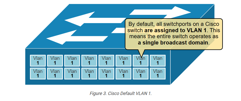
By default, all interfaces on a Cisco switch are in the same broadcast domain. Therefore, when a broadcast frame is received on any switch port, the switch forwards it out to all its other ports. At the same time, organizations want to isolate different users into separate broadcast domains. For example, the R&D department must be isolated from the HR department.
- R&D needs to keep their secret project work confidential.
- HR must protect sensitive information like employee salaries.
However, if they share the same broadcast domain, R&D’s BUM traffic reaches HR users, and HR traffic reaches R&D users. This creates security and privacy issues. By placing each department in its own broadcast domain, organizations keep traffic separated and improve both control and privacy.
But how do we separate some users into different broadcast domains? (if VLANs don’t exist)
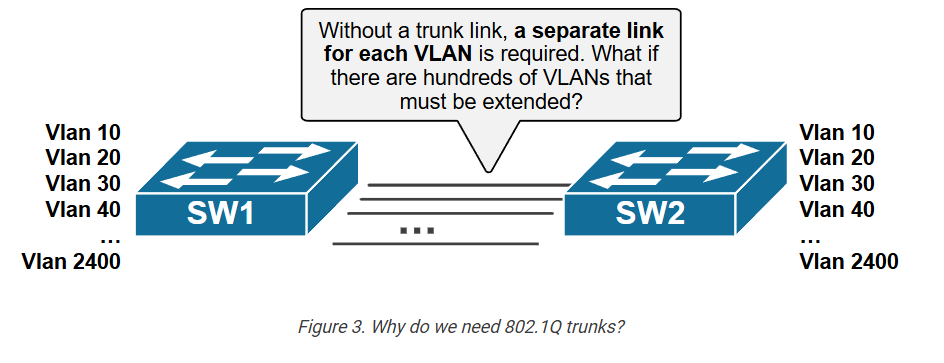
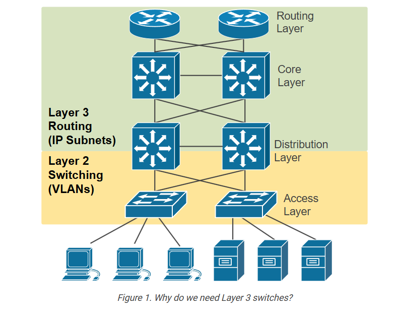
You must connect each different group of users to a different physical switch. But how many different physical switches can you have in the network? What if the organizations want to have hundreds or thousands of separate broadcast domains? Can you really have thousands of physical switches to isolate some BUM traffic from others? Of course not. At some point, people realized that there is another way – we can isolate broadcast domains logically.
What are VLANs?
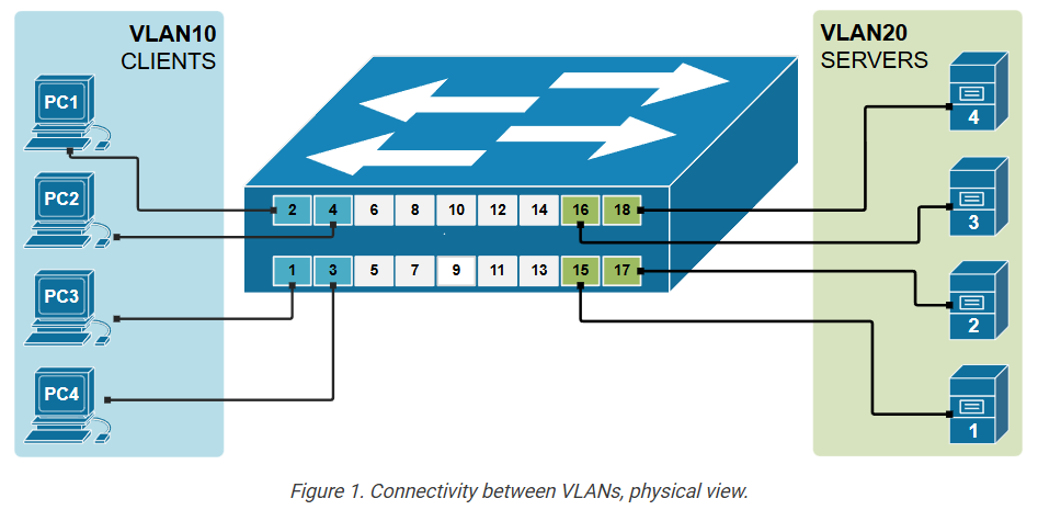
We have said that to create two separate LANs (such as one for servers and one for users), we must use two different physical switches, as shown in the diagram above. This approach is not scalable; imagine if your organization wants to have a thousand separate LANs, it has to have thousands of physical switches. This scaling limitation is the reason why Virtual LANs were introduced.
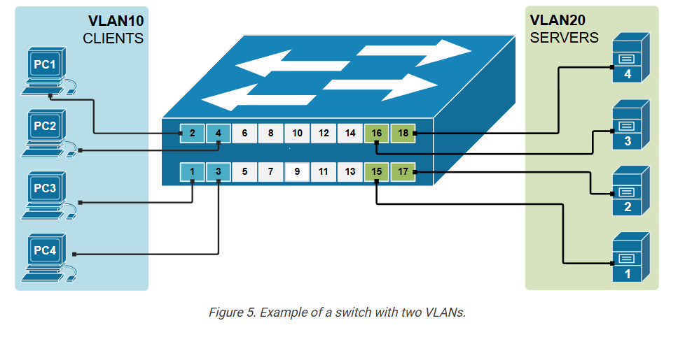
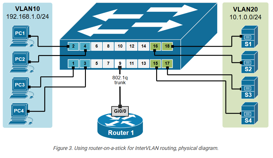
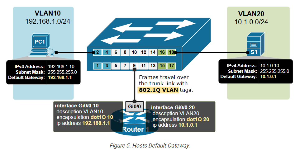
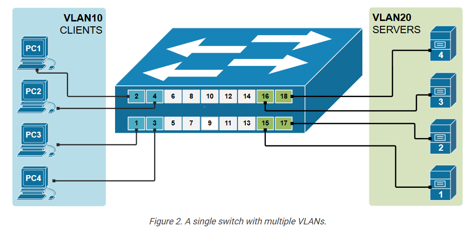
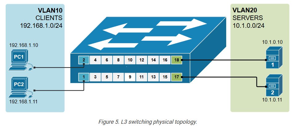
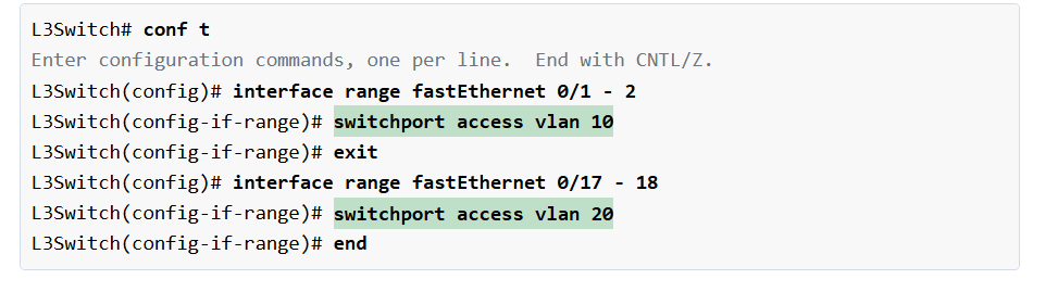
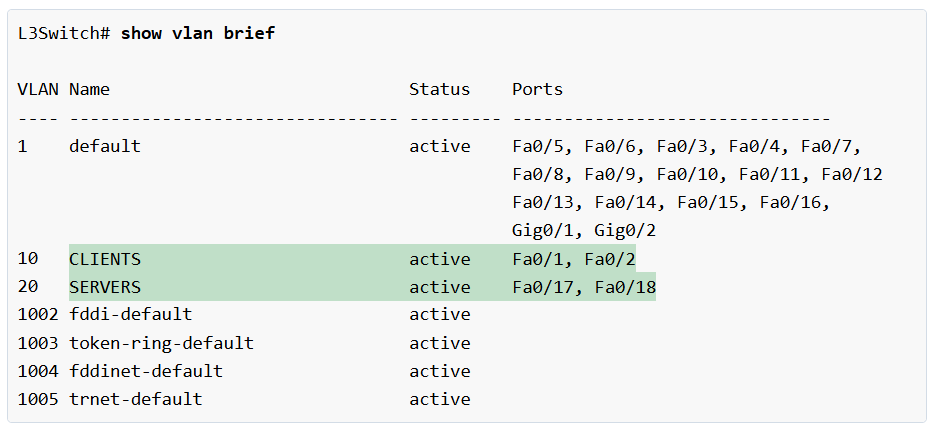
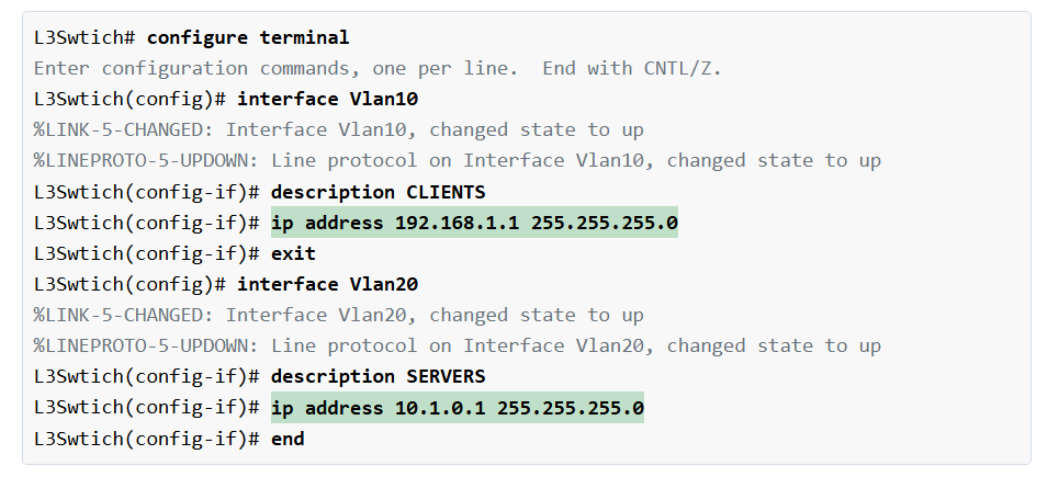
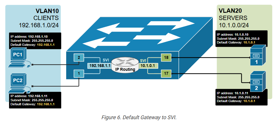
By using VLANs, a single switch can act as multiple logical switches and create multiple broadcast domains. This is done on a port-by-port basis. Using the following diagram as an example, the ports where the users are connected are configured to be part of VLAN10 (or, in other words, to be connected to virtual switch 10), and the ports where the servers are connected are configured to be part of VLAN20 (or in other words to be connected to virtual switch 20). The switch will then never forward a frame sent by any user to any of the servers and vice-versa because they are part of different broadcast domains.