Spanning Tree Protocol (STP)
History OF STP Protocol
The history of STP (Spanning Tree Protocol) begins in the early 1980s when computer networks were growing and engineers faced serious problems with network loops and broadcast storms in Ethernet switch environments. At that time, there was no automatic method to control redundant links between bridges (early switches). In 1985, a network engineer named Radia Perlman working at Digital Equipment Corporation (DEC) developed the Spanning Tree Algorithm. Her goal was to create a protocol that could automatically detect loops and block extra paths while still allowing redundancy for backup. This invention became the foundation of modern Ethernet loop prevention and is considered one of the most important breakthroughs in networking history.
Later, the Spanning Tree Algorithm was standardized by the IEEE as IEEE 802.1D Spanning Tree Protocol in 1990. This made STP an official global networking standard so that switches from different vendors could interoperate safely. Over time, improvements were introduced to make STP faster and more efficient, such as RSTP (Rapid Spanning Tree Protocol – IEEE 802.1w) and MSTP (Multiple Spanning Tree Protocol – IEEE 802.1s). Although many vendors now use faster technologies, the original STP concept created by Radia Perlman remains the core idea behind loop prevention in Ethernet networks.
Who is the owner of STP?
No single company owns STP. The original algorithm was invented by Radia Perlman, and the protocol is maintained and standardized by the IEEE. Because it is an open standard, all networking vendors (like Cisco, Juniper, HP, etc.) can implement STP in their switches. For this reason, Radia Perlman is widely known as the “Mother of the Internet” and the inventor of Spanning Tree Protocol, while IEEE is responsible for its official standardization and global use.
Radia Perlman For STP Protocol

What is STP Protocol
What is STP and how does it work?
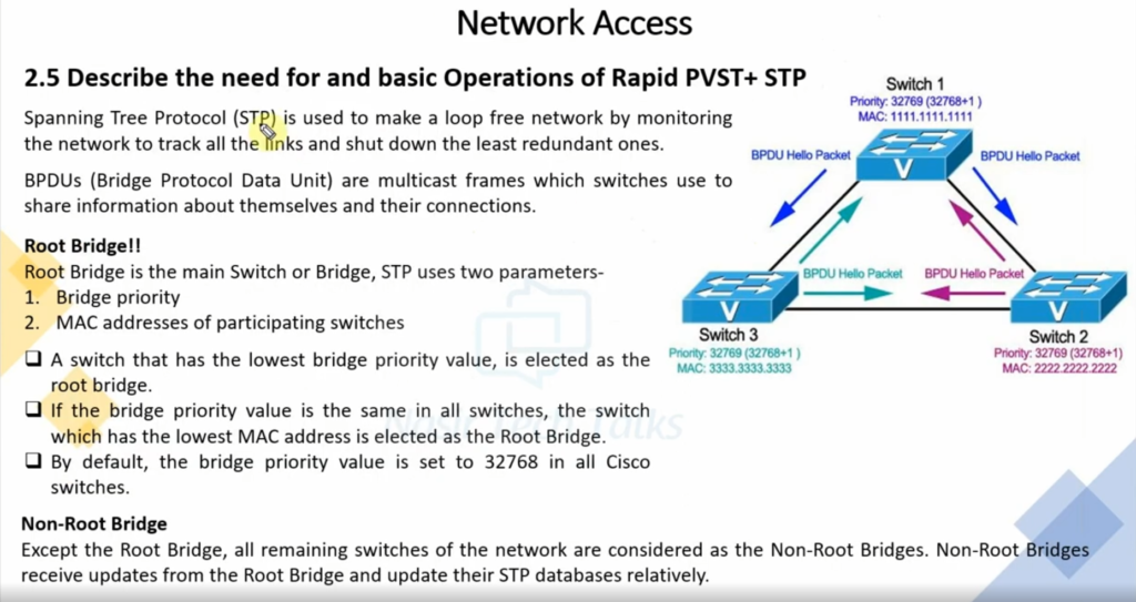
STP (Spanning Tree Protocol) is a network protocol used in Ethernet switched networks to prevent looping and broadcast storms when multiple switches are connected with redundant paths. In a network, redundancy is important for reliability, but if there are two or more active paths between switches, data frames can circulate endlessly, causing network loops, high bandwidth usage, and complete network failure. STP solves this problem by creating a logical loop-free topology. It works by automatically detecting all possible paths between switches and then blocking the extra redundant links while keeping only one active path for data forwarding. If the active path fails, STP quickly unblocks a backup path, ensuring continuous network connectivity.
In detail, STP works by selecting one switch as the Root Bridge, which becomes the reference point for the entire network. All other switches calculate the shortest path to the root bridge using a metric called path cost. Based on this calculation, STP assigns different roles to switch ports: Root Port (best path toward the root bridge), Designated Port (best path for a network segment), and Blocked Port (ports that would cause loops if they were active). Only root and designated ports forward traffic, while blocked ports remain in a standby state. STP exchanges special messages called BPDU (Bridge Protocol Data Units) between switches to share information about bridge IDs and path costs. Over time, STP converges to a stable topology where no loops exist. Modern versions such as Rapid STP (RSTP) make this process faster. Overall, STP is essential in enterprise networks to provide redundancy, stability, and protection from network outages caused by switching loops.
What are STP port states?
When STP is enabled on a network bridge, each port is set to one of five states to control frame forwarding:
- Disabled. The port does not participate in frame forwarding or STP operations.
- Blocking. The port does not participate in frame forwarding and discards frames received from the attached network segment. However, the port continues to listen for and process BPDUs.
- Listening. From the blocking state, the port transitions to the listening state. The port discards frames from the attached network segment or forwarded from another port. However, it receives BPDUs and redirects them to the switch module for processing.
- Learning. The port moves from the listening state to the learning state. It listens for and processes BPDUs but discards frames from the attached network segment or forwarded from another port. It also starts updating the address table with the information it’s learned. In addition, it processes user frames but does not forward those frames.
- Forwarding. The port moves from the learning state to the forwarding state and starts forwarding frames across the network segments. This includes frames from the attached network segment and those forwarded from another port. The port also continues to receive and process BPDUs, and the address table continues to be updated.
STP moves from the blocking state through the forwarding state in relatively short order, usually between 15 to 20 seconds for each state. Every port starts in the blocking state. If it’s been disabled, the port enters directly into the blocking state upon being enabled. STP balances the states across ports to avoid bridge looping, while still making redundancy possible.
spanning-tree mode <protocol mode>
For example, to enable Rapid STP (RSTP) on a switch, the administrator would run the following command:
spanning-tree mode rstp
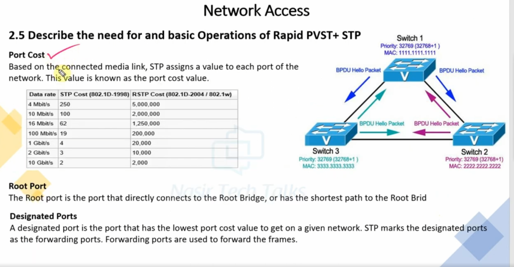
In addition to enabling STP, an administrator must select a root bridge to serve as the network’s central STP reference point. The administrator must also identify root ports and designated ports. A root port is a bridge port that forwards frames to the root bridge, and a designated port is a bridge port that forwards frames away from the root bridge.
How Wok STP
STP (Spanning Tree Protocol) is a network protocol that prevents loops and broadcast storms in Ethernet networks where multiple switches are connected with redundant links. Without STP, frames can circulate endlessly between switches, causing network congestion and complete network failure. STP works by creating a logical tree structure (spanning tree) where only one active path exists between any two switches, while extra paths are kept in a blocked state as backups. If the active link fails, STP automatically activates a blocked link to maintain network connectivity.
In detail, STP works through a step-by-step process. First, all switches exchange special control messages called BPDU (Bridge Protocol Data Units) to share information about their Bridge ID (priority and MAC address). The switch with the lowest Bridge ID is elected as the Root Bridge, which becomes the central reference point of the network. Next, each non-root switch calculates the shortest path cost to reach the Root Bridge and selects one port as its Root Port (the best path toward the root). For each network segment, STP then selects one Designated Port, which is responsible for forwarding traffic on that segment. All other ports that could cause loops are placed into a Blocked (Non-Designated) state to stop traffic from circulating endlessly.
After selecting port roles, STP transitions ports through different states to ensure stability before allowing data traffic. Ports move from Blocking → Listening → Learning → Forwarding. During Blocking and Listening, the ports do not forward data but only process BPDUs to ensure there is no loop. In the Learning state, the switch starts building its MAC address table but still does not forward user traffic. Finally, in the Forwarding state, the port sends and receives normal network traffic. If a link fails or a topology change occurs, STP recalculates the topology, selects new root and designated ports if necessary, and brings a blocked port into forwarding state to restore communication. This automatic process makes STP essential for providing both loop prevention and redundancy in enterprise networks.
What is STP, RSTP, and PVST
STP (Spanning Tree Protocol – IEEE 802.1D)
STP is the original loop-prevention protocol used in Ethernet switched networks. It prevents network loops and broadcast storms by creating a loop-free logical topology. STP works by electing a Root Bridge, calculating the shortest path to the root, and then blocking redundant ports while keeping one active path. Ports move through multiple states—Blocking, Listening, Learning, and Forwarding—before they start sending data. Because of these slow transitions, STP convergence time is high (around 30–50 seconds), which can cause noticeable network downtime during failures. STP is reliable but considered slow for modern networks.
RSTP (Rapid Spanning Tree Protocol – IEEE 802.1w)
RSTP is an improved and faster version of STP designed to reduce network downtime. It performs the same basic function—preventing loops—but with much faster convergence, usually within a few seconds. RSTP introduces new port roles such as Alternate Port and Backup Port, and simplifies port states into Discarding, Learning, and Forwarding. Instead of waiting for long timers like STP, RSTP uses rapid handshakes between switches to quickly detect failures and activate backup paths. RSTP is backward compatible with STP and is widely used in modern enterprise networks.
PVST (Per-VLAN Spanning Tree – Cisco)
PVST is a Cisco-specific implementation of STP that runs a separate STP instance for each VLAN. This allows better traffic optimization because each VLAN can have a different Root Bridge, improving load balancing across links. Traditional STP and RSTP create only one spanning tree for all VLANs, but PVST gives more control in VLAN-based networks. Cisco also provides Rapid PVST+, which combines the speed of RSTP with per-VLAN operation. PVST is commonly used in Cisco environments but is not vendor-neutral.
Key Differences (Quick View)
| Feature | STP | RSTP | PVST |
|---|---|---|---|
| Standard | IEEE 802.1D | IEEE 802.1w | Cisco proprietary |
| Convergence Speed | Slow (30–50 sec) | Fast (1–5 sec) | Depends on STP/RSTP |
| Spanning Tree | One for all VLANs | One for all VLANs | One per VLAN |
| Port Roles | Root, Designated, Blocked | Root, Designated, Alternate, Backup | Same as STP/RSTP |
| Usage | Old networks | Modern networks | Cisco VLAN networks |
Conclusion
- STP is reliable but slow and mostly outdated
- RSTP is fast, efficient, and best for modern networks
- PVST provides VLAN-level control and load balancing in Cisco networks
In real enterprise designs, RSTP or Rapid PVST+ is preferred to ensure fast recovery, redundancy, and stable network performance.
STP Slide