Hierarchical Networking Diagram Architecture

Network Designing is a process of placing the network devices (currently in use or to be used in the future) in such a manner that it follows all the Structured Engineering Principles which include Hierarchy, Modularity, Resiliency, and Flexibility. This Network Design often depends on the network size and requirements which are a critical factors for the successful implementation of any network.

Access Layer:

This layer consists of end devices (end-users, local servers, etc.) that have local access to the network.

  • The Access Layer (commonly referred to as the network edge) is where the end-user devices connect to the network.
  • It provides high-bandwidth connectivity.
  • It provides Layer 2 Switching capabilities.
  • Services like Port Security, Quality of Service (QoS), ARP Inspection are used in this layer.
  • Discovery and Configuration Services like CDP, LLDP also run in the Access Layer.
  • This layer plays a big role in protecting the network and malicious attacks because of its connection with the endpoints of the network.

Distribution Layer:

This layer basically provides policy-based connectivity and acts as a boundary between the Access Layer and the Core Layer. Data Filtering and Routing take place in this layer.

  • The Distribution Layer is mainly responsible for collecting/aggregating data from the Switches of the Access Layer and distributing it to the rest of the network.
  • It acts as a border as well as a connector to both the Access Layer and the Core Layer.
  • It provides policy-based security by using Access Control Lists (ACLs) and filtering.
  • The use of routing services (like EIGRP, OSPF. Etc.) also takes place in this layer.
  • It provides Redundancy and Load Balancing.

Core Layer:

This layer is often considered to be the Backbone of the network which provides fast transport between the switches present in the Distribution Layer of the network. The Core Layer is considered to be the Backbone of the network and acts as an aggregation point for multiple networks.

  • It consists of high-speed network devices responsible for switching packets as fast as possible.
  • It provides interconnectivity between the Distribution Layer devices.
  • It provides reliability and fault tolerance to maximize performance.
  • It also plays a crucial role in avoiding CPU-intensive packet manipulation caused by security services (restrictive ACLs), Quality of Service (QoS) classification, inspection, etc.

Enterprise Network Architecture

What is Enterprise Network Architecture?

Enterprise Network Architecture is the overall design and structure of a company’s entire computer network.

It defines how servers, switches, routers, firewalls, data centers, branch offices, and users are connected to securely share data, applications, and internet services.

👉 In simple words:
It’s the blueprint of how a large organization’s network is built and works together.

Main Goals of Enterprise Network Architecture

  • Connectivity: All users, servers, and offices can communicate.
  • Security: Data and systems are protected from internal and external threats.
  • Performance: Fast, stable, and reliable connections.
  • Scalability: Easy to expand as the company grows.
  • Manageability: Centralized monitoring and control of the entire network.
  • Redundancy: Backup links and servers for high availability.

3-Tier Enterprise Network Architecture (Cisco Standard Model)

Enterprise networks are usually built in 3 layers 👇

Core Layer (Network Backbone)?

  • High-speed backbone of the network.
  • Connects all distribution layers and data centers.
  • Focuses on speed, redundancy, and reliability.

Devices: High-end routers, Layer 3 switches, core firewalls.


Distribution Layer (Control & Management Layer)?

  • Connects access layer switches to the core.
  • Controls traffic with routing, VLANs, and access policies.
  • Acts as a bridge between users and the core network.

Devices:
Layer 3 switches, distribution routers, access control firewalls.


Access Layer (User Connectivity Layer)?

  • Provides direct connectivity to users and devices (PCs, printers, IP phones, Wi-Fi).
  • Controls who can access what.

Devices:
Access switches, wireless access points, edge firewalls.


Benefits of Good Enterprise Network Architecture?

  • High security and data protection
  • Fast and reliable communication
  • Centralized user and resource management
  • Easier troubleshooting and monitoring
  • Future-ready (scalable and flexible)

Network Devices Vendors and Models (Used in Data Center and ISP)

Router Vendors and Models (Used in Data Center and ISP)

Routers are used in ISPs and data centers to route traffic between networks and connect to the internet backbone. They support protocols like BGP, OSPF, and MPLS. Large organizations use high-performance routers that can handle huge amounts of data traffic. Common router vendors include Cisco, Juniper Networks, Nokia, and Huawei. Popular models include Cisco ASR 9000 Series, Juniper MX960, Nokia 7750 Service Router, and Huawei NetEngine 8000 Series. These routers are used for high-speed routing, ISP backbone connectivity, and large network traffic management.

Switch Vendors and Models (Used in Data Center)

Switches are used inside data centers to connect servers, storage systems, and other network devices. They provide high-speed communication and support technologies such as VLAN, VXLAN, and high-speed Ethernet (10G/40G/100G). Common switch vendors include Cisco, Arista Networks, Juniper Networks, and Huawei. Popular models include Cisco Nexus 9000 Series, Arista 7050X Series, Juniper QFX5120, and Huawei CloudEngine 12800. These switches are commonly used in data center spine-leaf architectures for fast and reliable server connectivity.

Firewall Vendors and Models (Used for Network Security)

Firewalls are used in data centers and ISP networks to protect the network from cyber threats, unauthorized access, and malicious traffic. They inspect and filter network traffic based on security rules. Major firewall vendors include Palo Alto Networks, Fortinet, Cisco, and Check Point Software Technologies. Common firewall models include Palo Alto Networks PA‑7000 Series, Fortinet FortiGate 6000 Series, Cisco Firepower 4100 Series, and Check Point Quantum 26000. These firewalls provide advanced security features such as intrusion prevention, deep packet inspection, and application control to keep networks safe.

Cisco Core Layer Switch Models

Core Layer Overview

Core Layer = The backbone of the network.

  • Connects distribution layers and data centers.
  • Focuses on high speed, redundancy, and reliability.
  • Minimal packet processing — primarily switches traffic quickly.

Key Features of Core Layer Switches:

  • Very high throughput (10GbE, 40GbE, 100GbE, or higher)
  • Redundant power supplies and fans
  • High port density
  • Advanced routing capabilities (Layer 3)
  • Support for virtualization and high availability

Popular Cisco Core Layer Switch Models

ModelDescription / Use Case
Cisco Catalyst 9600 SeriesModular core switch for large campus networks. High performance, redundant, and scalable.
Cisco Catalyst 9500 SeriesFixed high-end core switch for enterprise campus networks. Layer 3 routing, high throughput.
Cisco Nexus 9000 SeriesData center core & spine switch. Very high bandwidth, low latency, designed for cloud-scale networks.
Cisco Nexus 7000 SeriesModular data center core switches (older generation, still widely used).
Cisco ASR 1000 / 9000 SeriesCore router-class devices, sometimes used as core switches in large enterprise WANs.

Core Layer Design Principles

  • High-speed backbone: Handles massive traffic between distribution switches.
  • Redundancy: Dual power supplies, redundant supervisor modules, and link aggregation.
  • Layer 3 Routing: Supports inter-VLAN routing and advanced routing protocols (OSPF, EIGRP, BGP).
  • Minimal Latency: Avoids unnecessary processing; focuses on fast packet forwarding.
  • Scalability: Can expand port density or bandwidth as enterprise grows.

Summary

Core Layer Switch = Backbone Switch

  • Handles high-speed traffic between distribution layers
  • Cisco models: Catalyst 9600 / 9500, Nexus 9000, Nexus 7000
  • Focus: High throughput, redundancy, scalability, and Layer 3 routing

Cisco Distribution Layer Switch

Distribution Layer Overview

Distribution Layer = The aggregation layer between the Core Layer and Access Layer.

  • Aggregates multiple access switches.
  • Implements routing, policies, and security controls.
  • Controls traffic flow between VLANs and subnets.

Key Features of Distribution Layer Switches:

  • Layer 3 routing between VLANs/subnets
  • Policy enforcement (ACLs, QoS)
  • Redundancy and link aggregation
  • High port density (but less than core)
  • Stackable or modular depending on network siz

Popular Cisco Distribution Layer Switch Models

ModelDescription / Use Case
Cisco Catalyst 9300 SeriesStackable distribution switch for enterprise campus networks. Supports Layer 3 routing, PoE+, and advanced security.
Cisco Catalyst 9400 SeriesModular distribution switch for large campus networks. High scalability, redundancy, and advanced features.
Cisco Nexus 9300 SeriesData center leaf/distribution switch for aggregating servers and connecting to Nexus core switches.
Cisco Catalyst 3850 SeriesOlder stackable distribution switch with Layer 3 routing and PoE support. Still used in many campuses.
Cisco Catalyst 4500 SeriesModular distribution switch for medium-to-large enterprise campuses. Supports high-density ports and Layer 3 features.

Distribution Layer Design Principles

  • Routing Between VLANs:
    Supports inter-VLAN routing so users in different subnets can communicate.
  • Policy Enforcement:
    Implements ACLs, QoS, and security policies for traffic control.
  • Aggregation:
    Connects multiple access switches and uplinks to the core layer.
  • Redundancy & High Availability:
    Supports dual supervisors, redundant links, and stacking for resilience.
  • Scalability:
    Can handle more users or devices as the campus grows.

Simple Recommendation

Enterprise SizeCisco Distribution Switch Suggestion
Small-to-Medium CampusCatalyst 9300 Series
Large Campus / HQCatalyst 9400 Series
Data Center AggregationNexus 9300 Series
Medium-to-Large CampusCatalyst 4500 Series

Summary

Distribution Layer Switch = Aggregation / Policy Layer

  • Connects Access Layer to Core Layer
  • Cisco models: Catalyst 9300, 9400, 4500, Nexus 9300
  • Focus: Routing, security policies, redundancy, and traffic aggregation

Cisco Access Layer Switches

Access Layer Overview?

Access Layer = The layer where end devices connect to the network.

  • Connects PCs, laptops, IP phones, printers, and Wi-Fi access points.
  • Provides VLAN segmentation, port security, and PoE (Power over Ethernet).
  • Controls who can access the network.

Key Features of Access Layer Switches:

  • Layer 2 switching (sometimes Layer 3 for small networks)
  • PoE/PoE+ support for devices like IP phones and wireless APs
  • VLAN segmentation for traffic isolation
  • Port security and access control
  • Stackable for scalability

Popular Cisco Access Layer Switch Models?

ModelDescription / Use Case
Cisco Catalyst 9200 SeriesStackable access switch for enterprise campus networks. PoE+, Layer 2/3 support, advanced security.
Cisco Catalyst 2960-X / 2960-XR SeriesFixed access switch, Layer 2 switching with optional Layer 3 static routing. PoE support for IP phones and APs.
Cisco Catalyst 1000 SeriesSmall office / branch office access switch. Simple deployment, PoE, basic security features.
Cisco Catalyst 2960-L SeriesEntry-level access switch for small campuses and branch offices. PoE support, stackable, compact design.
Cisco Catalyst 9200L SeriesEconomical version of 9200, stackable, Layer 2/3, PoE+ support.

Access Layer Design Principles?

  • End-User Connectivity:
    Connects all desktops, laptops, IP phones, and Wi-Fi APs.
  • VLAN Segmentation:
    Groups devices into logical networks (e.g., HR VLAN, Sales VLAN).
  • PoE/PoE+:
    Powers devices like IP phones and wireless access points without extra power cables.
  • Port Security:
    Limits which devices can connect to specific ports to prevent unauthorized access.
  • Scalability:
    Stackable switches allow multiple switches to act as one, simplifying management.

In Short

Access Layer Switch = User / Device Connectivity Layer

  • Provides network access to all end devices
  • Supports PoE, VLANs, and security
  • Common Cisco models: Catalyst 9200, 2960-X/XR, 1000

Catalyst 2960-X and 2960-XR Switches

Data Center Network Like Google,Facebook,Youtube

A Data Center Network (DCN) is a specialized network architecture used inside a data center to connect servers, storage systems, switches, routers, and other IT equipment. The main purpose of a DCN is to provide high-speed communication, low latency, high availability, and secure data transfer between all devices in the data center. It enables organizations to store, process, and manage large volumes of data efficiently while supporting applications, cloud services, virtualization, and enterprise workloads.

In a data center environment, thousands of servers and networking devices must communicate with each other continuously. A DCN connects these devices through high-performance switches and routers so that data can move quickly between systems. For example, when a user accesses a website or cloud application, the request travels through the data center network to the appropriate server, which processes the request and sends the response back through the same network infrastructure.

Data Center Networks are designed using different network topologies such as three-tier architecture (Core, Aggregation, and Access layers) or modern spine-leaf architecture. These designs help distribute traffic efficiently, reduce network congestion, and provide redundancy. If one link or device fails, the DCN automatically reroutes traffic through another path to maintain service availability.

Another important feature of DCN is scalability. As organizations grow, they need to add more servers and storage devices to handle increased workloads. A well-designed DCN allows new devices to be integrated without disrupting existing services. Technologies such as virtualization, software-defined networking (SDN), and high-speed fiber connectivity are commonly used in modern data center networks.

Security and reliability are also critical in a Data Center Network. Since sensitive business data and applications are hosted in data centers, DCNs include firewalls, intrusion detection systems, network segmentation, and monitoring tools to protect the infrastructure from cyber threats and unauthorized access. This ensures that the network remains stable, secure, and continuously available for users and applications.

Main Goals of a Data Center

The main goals of a Data Center Network (DCN) are to ensure that data, applications, and services inside a data center operate efficiently, reliably, and securely. A DCN is designed to support large-scale computing environments where many servers, storage systems, and network devices must communicate with each other continuously.

High Performance:
One of the primary goals of a data center network is to provide high-speed data communication between servers, storage devices, and users. Applications such as cloud computing, databases, and virtualization require very fast data transfer with minimal delay. Therefore, DCNs are designed with high-bandwidth links and efficient switching technologies to handle large amounts of traffic.

Low Latency:
Low latency means reducing the time it takes for data to travel from one device to another. Many modern applications like real-time analytics, financial transactions, and online services require extremely fast response times. A well-designed DCN ensures that data packets move quickly through the network with minimal delay.

High Availability and Reliability:
Data centers must operate 24/7 without interruption. The network is designed with redundancy using multiple switches, links, and paths. If one network device or link fails, traffic can automatically move through another path. This ensures that services remain available even during hardware failures or maintenance.

Scalability:
Another important goal is scalability. As companies grow, they need to add more servers, storage, and networking equipment. A good DCN design allows the infrastructure to expand easily without affecting existing operations. Modern architectures like spine-leaf help data centers scale efficiently.

Efficient Traffic Management:
Data center networks must manage both north-south traffic (between users and servers) and east-west traffic (between servers inside the data center). Proper load balancing, routing, and switching techniques help distribute traffic evenly and prevent network congestion.

Security:
Since data centers store critical business and customer information, security is essential. DCNs include security mechanisms such as firewalls, access control policies, network segmentation, and monitoring systems to protect against cyber threats and unauthorized access.

Overall, the main goal of a Data Center Network is to provide a fast, reliable, scalable, and secure environment for hosting applications, storing data, and delivering services to users around the world.

Data Center Network Architecture

Data Center Network Architecture refers to the design and structure used to connect servers, storage devices, switches, and other networking equipment inside a data center. The architecture defines how network devices are organized, how data flows between them, and how the network ensures high performance, scalability, and reliability. A well-designed architecture helps the data center handle large amounts of traffic efficiently and maintain continuous service availability.

One common architecture used in traditional data centers is the three-tier architecture, which consists of three layers: Core Layer, Aggregation Layer, and Access Layer. The Access Layer connects directly to servers and storage devices. The Aggregation Layer acts as an intermediate layer that aggregates traffic from multiple access switches and applies policies such as routing and security. The Core Layer is the backbone of the network and provides high-speed connectivity between different parts of the data center and external networks.

Modern data centers often use the spine-leaf architecture, which is designed to handle large-scale cloud and virtualization environments. In this architecture, leaf switches connect directly to servers, and spine switches connect all leaf switches together. Every leaf switch connects to every spine switch, creating multiple equal paths for data. This design reduces latency and improves network performance, especially for east-west traffic (server-to-server communication).

Another important aspect of data center network architecture is redundancy and high availability. Multiple switches, links, and routing paths are used so that if one device or connection fails, the network can continue operating without interruption. Technologies such as load balancing, link aggregation, and virtualization help ensure smooth traffic flow and efficient resource utilization.

Modern architectures also incorporate technologies like software-defined networking (SDN) and network virtualization. These technologies allow network administrators to manage and configure the data center network through software rather than manual hardware configuration. This improves flexibility, automation, and scalability in large enterprise and cloud data centers.

Overall, Data Center Network Architecture focuses on creating a high-speed, scalable, reliable, and secure network infrastructure that supports the massive computing and storage requirements of modern applications and services.

Why Spine-Leaf Architecture is Used in a Data Center

Why Spine-Leaf Architecture is Used in a Data Center

Spine-Leaf architecture is used in modern data centers to provide high performance, low latency, and better scalability compared to traditional network designs. In this architecture, there are two main layers: Spine switches and Leaf switches. Leaf switches connect directly to servers and storage devices, while spine switches act as the high-speed backbone connecting all leaf switches. Every leaf switch connects to every spine switch, which creates multiple paths for data to travel.

The main reason for using spine-leaf architecture is to support large amounts of east-west traffic inside data centers. East-west traffic means communication between servers within the same data center. In cloud computing, virtualization, and big data environments, servers constantly communicate with each other. Spine-leaf architecture ensures that this server-to-server communication happens quickly and efficiently.

Another reason is low latency and consistent performance. Since any server can reach another server in only two hops (Leaf → Spine → Leaf), the network delay is very small. This helps applications such as cloud services, virtualization platforms, and distributed databases perform better.

Spine-leaf architecture also provides high scalability. When the data center grows and more servers are added, administrators can simply add more leaf switches or spine switches without redesigning the entire network. This makes it very suitable for modern data centers used by large companies and cloud providers.

High availability and redundancy are also key benefits. Because each leaf switch connects to multiple spine switches, there are multiple paths for traffic. If one link or spine switch fails, traffic can automatically use another path, keeping the network operational.


Benefits of Spine-Leaf Architecture

1. Low Latency
Data usually travels only two hops between servers, which reduces delay.

2. High Bandwidth
Multiple paths between switches provide high network throughput and better performance.

3. Better Scalability
New switches or servers can be added easily without major network redesign.

4. Efficient East-West Traffic Handling
Ideal for server-to-server communication common in virtualization and cloud environments.

5. High Redundancy
Multiple connections between leaf and spine switches prevent single points of failure.


Comparison: Spine-Leaf vs Three-Tier Architecture

FeatureSpine-Leaf ArchitectureThree-Tier Architecture
Network Layers2 Layers (Spine & Leaf)3 Layers (Core, Aggregation, Access)
LatencyVery LowHigher compared to spine-leaf
Traffic FlowOptimized for east-west trafficMainly designed for north-south traffic
ScalabilityEasy to scaleScaling is more complex
Network PathsMultiple equal pathsLimited paths
Use CaseModern cloud and large data centersTraditional enterprise networks

Summary:
Spine-leaf architecture is widely used in modern data centers because it provides high speed, low latency, better scalability, and strong redundancy, making it ideal for cloud computing and virtualization environments. In contrast, the traditional three-tier architecture is more suitable for older enterprise networks where most traffic flows between users and servers rather than between servers themselves.

Data Center Switch Models

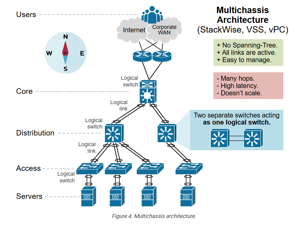
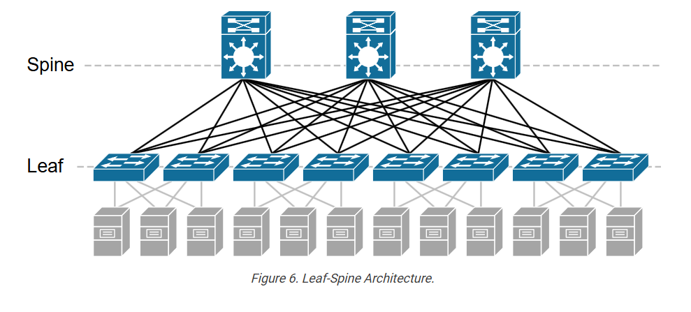
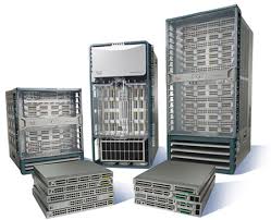
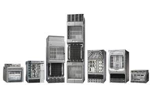
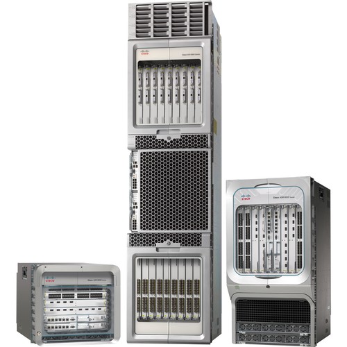
In modern data center networks, Cisco provides a wide range of Nexus series switches that are commonly used for spine–leaf architecture. In this design, leaf switches connect servers and storage, while spine switches act as the high-speed backbone connecting all leaf switches. Below are some commonly used Cisco spine and leaf switch models explained paragraph-wise.

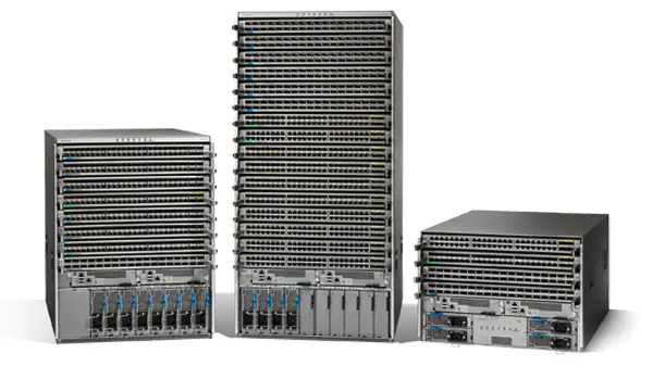
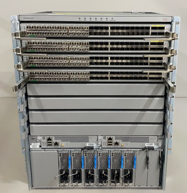
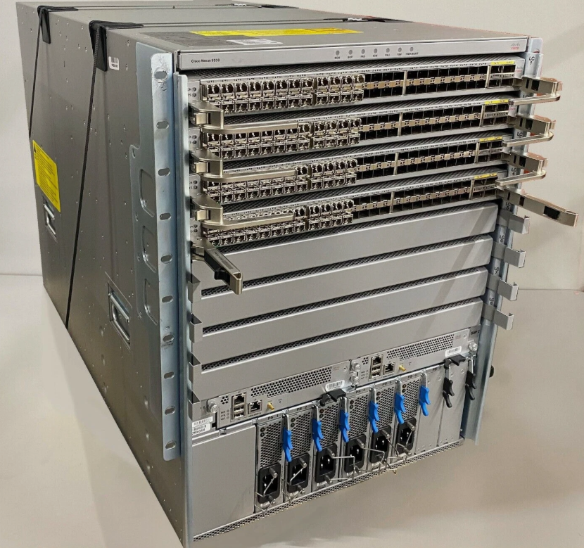
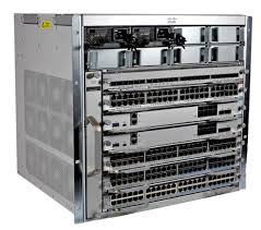
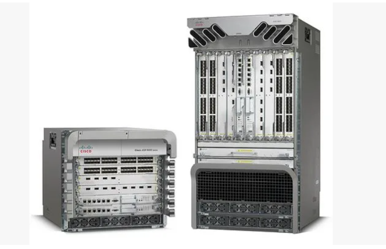
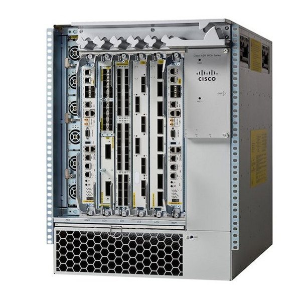
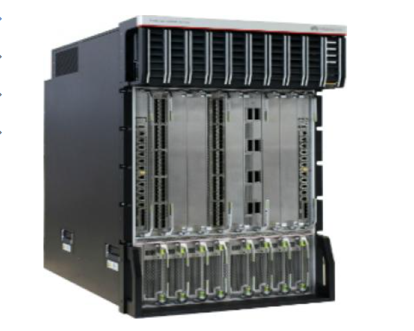
Cisco Nexus 9500 Series (Spine Switch):
The Cisco Nexus 9500 Series is a modular chassis-based switch widely used as a spine or core switch in large data centers. It provides very high port density and supports high-speed interfaces such as 40G, 100G, and 400G Ethernet. Because of its large switching capacity and scalability, it is typically deployed at the spine layer to interconnect many leaf switches and handle large volumes of east-west traffic between servers.

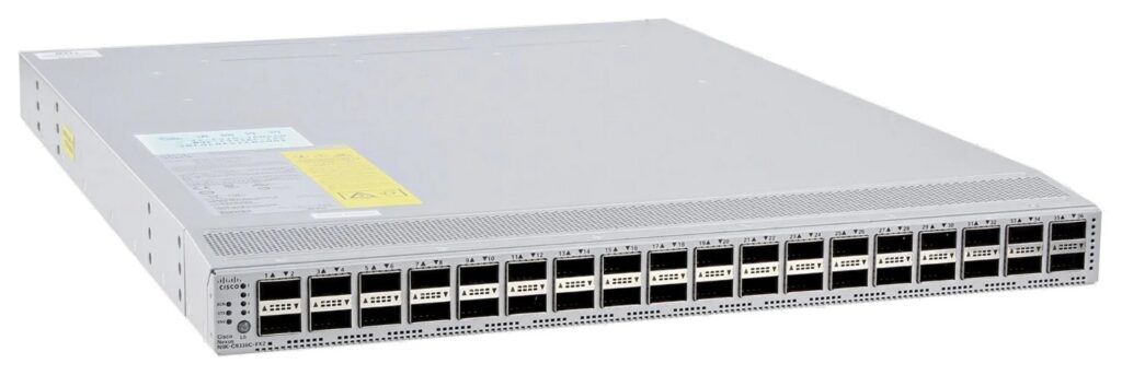
Cisco Nexus 9332C (Spine Switch):
The Cisco Nexus 9332C is a compact fixed switch that offers 32 ports of 100-Gigabit Ethernet. It is often used as a spine switch in medium-sized data center fabrics. This model is suitable for organizations that need high-speed connectivity between leaf switches but do not require a large modular chassis system.

Cisco Nexus 9364C (Spine or Aggregation Switch):
The Cisco Nexus 9364C provides 64 ports of 100-Gigabit Ethernet, making it ideal for high-bandwidth spine-leaf networks. It can operate as a spine switch or aggregation switch, depending on the network design. Its high port density and throughput make it suitable for cloud environments and large enterprise data centers.

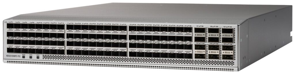
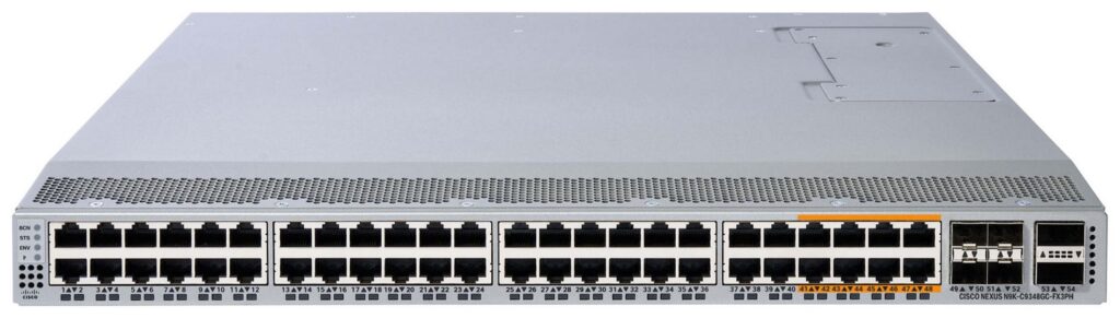
Cisco Nexus 93180YC‑FX (Leaf Switch):
The Cisco Nexus 93180YC-FX is a very popular leaf switch used in many enterprise and cloud data centers. It supports 48 ports of 10G/25G Ethernet for server connections and 6 ports of 40G/100G for uplinks to spine switches. This model is typically installed as a Top-of-Rack (ToR) switch, connecting servers in a rack to the spine network.

Cisco Nexus 9372PX (Leaf Switch):
The Cisco Nexus 9372PX is another widely used leaf switch that provides 48 ports of 10-Gigabit Ethernet and 6 ports of 40-Gigabit uplinks. It is commonly deployed in enterprise data centers where servers require reliable 10G connectivity and high-speed uplinks to the spine layer.

Cisco Nexus 93128TX (Leaf Switch):
The Cisco Nexus 93128TX is designed for environments requiring a large number of 10G server connections. It provides 48 ports of 10GBASE-T and multiple 40G uplinks to connect to spine switches. It is frequently used in data centers where many servers use copper Ethernet connections instead of fiber.

Summary:
In Cisco-based data center architecture, spine switches such as the Nexus 9500, 9332C, and 9364C provide the high-speed backbone, while leaf switches like the Nexus 93180YC-FX, 9372PX, and 93128TX connect servers and storage systems. Together, these switches form a scalable and high-performance spine-leaf network fabric used in modern enterprise and cloud data centers.

Arista Leaf and Spine Switch Models

Arista 7050X3 Series (Leaf Switch):
The Arista 7050X3 Series is widely used as a leaf switch in cloud and enterprise data centers. It supports 10G, 25G, and 100G Ethernet ports, making it ideal for connecting servers and storage devices. These switches are commonly deployed as Top-of-Rack (ToR) switches in spine-leaf architecture.

Arista 7060X Series (Leaf / Spine Switch):
The Arista 7060X Series can function as either a leaf switch or a small spine switch depending on the network size. It provides high-speed 100G connectivity and is used in scalable data center fabric networks.

Arista 7500R Series (Spine Switch):
The Arista 7500R Series is a modular spine/core switch used in large hyperscale and cloud data centers. It offers very high port density and large switching capacity to handle heavy east-west traffic between servers.


Huawei Leaf and Spine Switch Models

Huawei CloudEngine 6850 Series (Leaf Switch):
The Huawei CloudEngine 6850 Series is commonly used as a leaf switch in enterprise data centers. It provides 25G server ports and 100G uplinks to connect to spine switches.

Huawei CloudEngine 8850 Series (Spine Switch):
The Huawei CloudEngine 8850 Series is designed as a spine switch in large data center fabrics. It supports high-bandwidth 100G connectivity and provides low latency for data center traffic.

Huawei CloudEngine 16800 Series (Core / Spine Switch):
The Huawei CloudEngine 16800 Series is a high-end modular switch used as a core or spine device in large enterprise and telecom data centers.


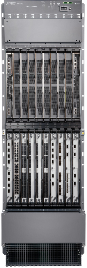
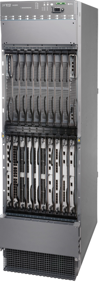
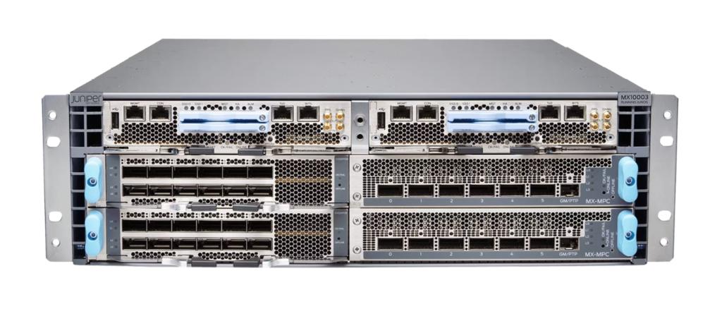
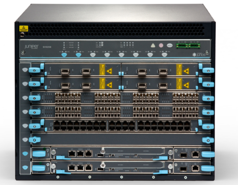
Juniper Leaf and Spine Switch Models

Juniper QFX5120 Switch (Leaf Switch):
The Juniper QFX5120 is commonly deployed as a leaf switch in data center fabric architecture. It supports 10G/25G server connectivity and 100G uplinks to spine switches.

Juniper QFX5200 Switch (Leaf / Spine Switch):
The Juniper QFX5200 can operate as either a leaf switch or small spine switch in data center networks. It provides high-performance 100G Ethernet ports.

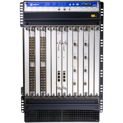
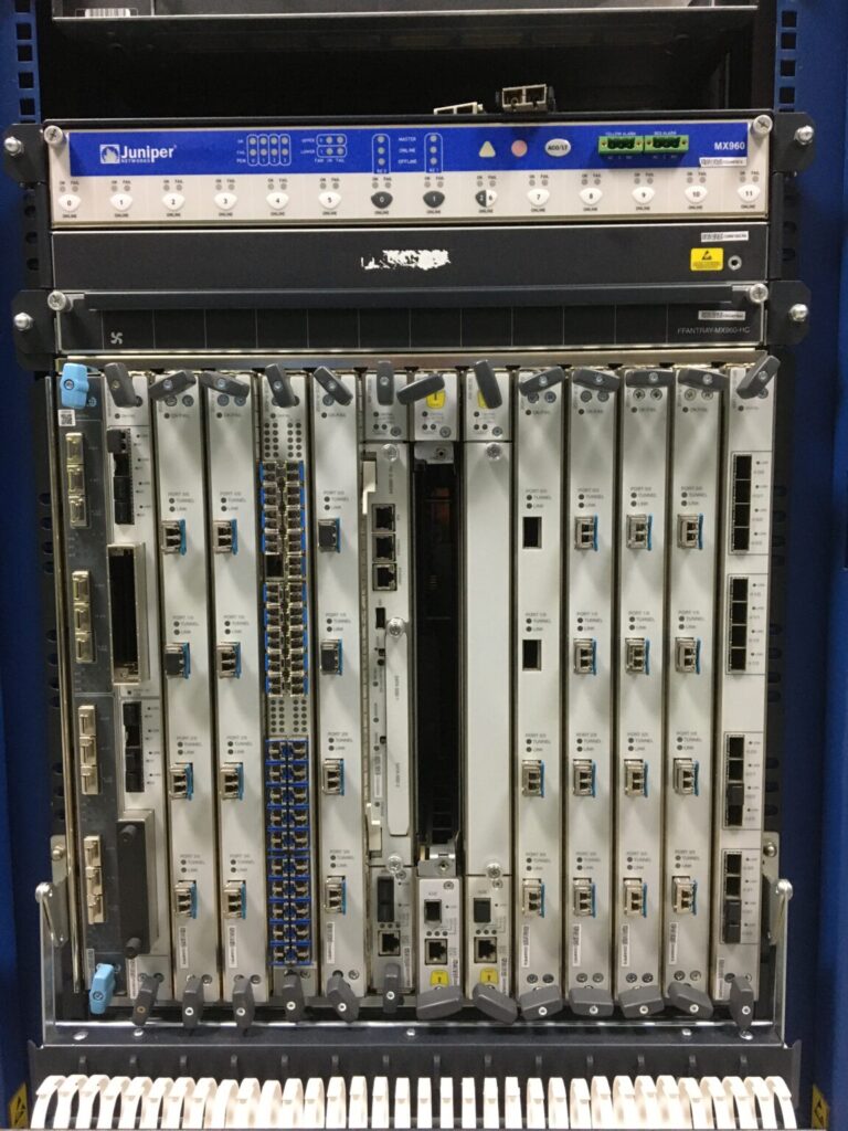
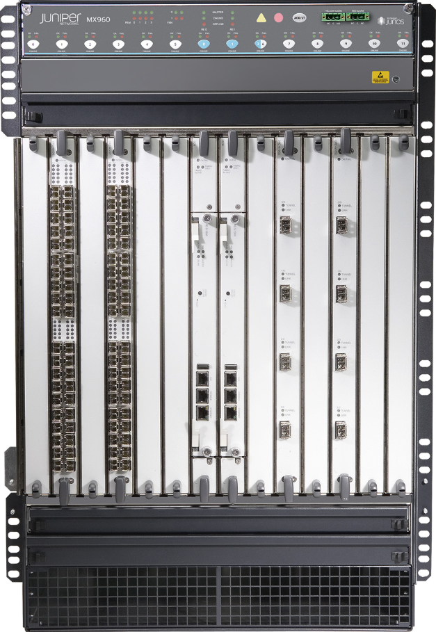
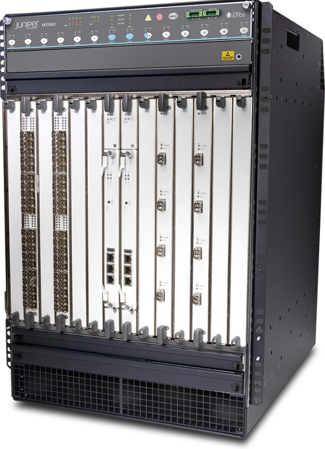
Juniper QFX10008 (Spine Switch):
The Juniper QFX10008 is a modular spine switch designed for large-scale data center fabrics. It offers very high switching capacity and large port density for connecting many leaf switches.

1. Cisco Data Center Spine / Core Switch Models

ModelPurpose
Cisco Nexus 9500 SeriesModular core/spine switch used in large enterprise and cloud data centers.
Cisco Nexus 9332CFixed 32×100G spine switch used in spine-leaf fabric networks.
Cisco Nexus 9364CUsed as spine or aggregation switch with high-speed 100G ports.
Cisco Nexus 92300YC SeriesFlexible switch that can work as leaf or spine in modern data centers.

Data Center Core / Spine Switches

Purpose:

  • High-speed backbone connecting all leaf/access switches.
  • Handles east-west traffic (server-to-server inside the DC).
  • Ensures low latency, high throughput, and redundancy.

Popular Vendors & Models:

VendorModelNotes
CiscoNexus 9000, Nexus 9500Spine switches, high throughput, VXLAN & ACI support
Arista7280R, 7500RSpine switches for cloud-scale DCs, low latency
JuniperQFX10000, QFX5100High-performance spine, VXLAN support
HPE / Aruba8400, 8320Modular switches for enterprise DCs

Data Center Leaf / Access Switches?

Purpose:

  • Connect servers, storage, and hypervisors.
  • Handles east-west traffic and provides PoE if needed (mainly in campus DCs).

Popular Vendors & Models:?

VendorModelNotes
CiscoNexus 9300, Catalyst 9500 (DC variant)Leaf switches, VXLAN, high-density ports
Arista7050X, 7060XLeaf switches for high-density 10/25/40/100GbE
JuniperQFX5100, QFX5110Leaf switches with EVPN / VXLAN support
HPE / Aruba8320, 8325Leaf switches, scalable for enterprise DC
 

2. Arista Data Center Spine Switch Models

ModelPurpose
Arista 7500R SeriesLarge core/spine switch used in hyperscale data centers.
Arista 7800R3 SeriesHigh-capacity 400G spine switch for large cloud data centers.
Arista 7280R SeriesSpine or aggregation switch used in large networks.
 

3. Juniper Data Center Spine Switch Models

ModelPurpose
Juniper QFX10002Fixed spine switch used in medium-scale data centers.
Juniper QFX10008Modular spine switch used in large data center fabrics.
Juniper QFX10016Very large core data center switch with high port density.

4. Huawei Data Center Spine Switch Models

ModelPurpose
Huawei CloudEngine 16800 SeriesLarge modular core data center switch supporting very high capacity.
Huawei CloudEngine 8850 SeriesUsed as 100G spine switch in data center networks.
Huawei CloudEngine 12800 SeriesCore switching platform for large enterprise networks.
 

Cisco Nexus 9500 Series Switches

Nexus 9500 48p 1/10GBaseT and 4p 100G line card

Cisco Nexus 9300 Series Network Switches

Cisco Nexus 9508 2x N9K-SUP-A 4x N9K-X9564PX + 96x SFP-10G-SR 13U Network Switch

Cisco Catalyst 9400 Series

Cisco Data Center Switch Price in INDIA

Here is a price list for common Cisco Nexus 9300 and 9500 data-center switches in India (approximate market prices; actual price varies by license, modules, and condition).

1. Cisco Nexus N9K‑C93180YC‑EX

  • Approx price: ₹8,18,000 in India.
  • Ports: 48 × 10/25G + 6 × 40/100G uplinks.
  • Use: Leaf switch in spine-leaf architecture connecting servers.

2. Cisco Nexus N9K‑C93180YC‑FX

  • Approx price: ₹6,40,000 – ₹7,00,000.
  • Use: Data-center leaf switch for high-speed server connectivity.

3. Cisco Nexus 93240YC‑FX2

  • Approx price: ₹13,00,000+.
  • Ports: 25G access ports with 100G uplinks.
  • Use: Leaf switch in large enterprise or cloud data centers.

4. Cisco Nexus 9300‑GX 9316D

  • Approx price: ₹19,00,000+.
  • Use: High-performance leaf/spine switch for hyperscale data centers.

Typical Nexus 9300 price range in India:

  • ₹1,00,000 (refurbished) → ₹19,00,000+ depending on model.

1. Cisco Nexus 9504

  • Approx price: ₹7,80,000+ (base chassis).
  • Use: Spine or core switch in large data centers.

2. Cisco Nexus 9332C

  • Approx price: ₹14,00,000+.
  • Ports: 32 × 100G.
  • Use: Spine switch in spine-leaf architecture.

Typical Nexus 9500 price range in India:

  • ₹7,00,000 → ₹40,00,000+ depending on modules and port cards.

LayerSwitch ModelRole
SpineCisco Nexus 9500Data center backbone
LeafCisco Nexus 9300Server connectivity
  • Cisco Nexus 9300: Leaf switch (₹1 lakh – ₹19 lakh).
  • Cisco Nexus 9500: Spine/core switch (₹7 lakh – ₹40 lakh+).

Data Center Router Models

Below are common Data Center Router models and their purpose. These routers are used to connect the data center to WAN, ISP networks, and other data centers and handle large routing traffic using protocols like BGP, OSPF, MPLS, and EVPN.


1. Cisco Data Center Router Models

Cisco ASR 9000 Series Router

Purpose:

  • Used as data center edge router or service provider edge router.
  • Supports very high bandwidth (10G, 40G, 100G).
  • Used for Data Center Interconnect (DCI) and large ISP networks.
  • Handles huge traffic with carrier-grade routing features.

Typical use:
Data center → Internet / ISP connectivity.


Cisco NCS 5500 Series Router

Purpose:

  • High-performance router for service provider and data center backbone networks.
  • Supports 100G interfaces and MPLS routing.
  • Used in large telecom or cloud networks.

Cisco ASR 9001 Router

Purpose:

  • Compact router used in small or medium data centers.
  • Handles WAN routing and data center edge connectivity.
  • Supports 10G Ethernet routing.

2. Juniper Data Center Router Models

Juniper MX960 Router

Purpose:

  • High-capacity core or edge router for large data centers.
  • Used for MPLS routing, BGP peering, and DCI connectivity.
  • Commonly deployed by ISPs and cloud providers.

3. Huawei Data Center Router Models

Huawei NetEngine 8000 Series Router

Purpose:

  • Used as core or edge router in modern data centers.
  • Supports 100G / 400G interfaces and advanced routing protocols.
  • Designed for 5G, cloud data centers, and backbone networks.

In a data center network, routers are used to connect the data center to external networks, ISPs, WAN networks, and other data centers. They handle large-scale routing using protocols such as BGP, OSPF, MPLS, and EVPN. Cisco provides several high-performance router platforms designed for enterprise and service-provider data centers.

Nokia 7750 Service Provider Router

Nokia 7750SR 7750SR-7S 13RU System capacity 57.6 Tb/s

Nokia 7360 ISAM FX-16 OLT FTTH Networking

NOKIA 7360 ISAM FX-8 OLT FTTH Networking

Huawei largest Router NE9000 for 400G

Cisco ASR Router Price in India

1. Cisco ASR1001‑X Router

  • Price in India: ₹1,40,000 – ₹11,00,000 depending on configuration
  • Throughput: 2.5–20 Gbps
  • Use: Enterprise WAN edge / Data-center edge router.

2. Cisco ASR1001X‑10G‑K9 Router

  • Price: ₹13,00,000 – ₹15,00,000
  • Interfaces: 10G WAN ports
  • Use: Data-center edge routing, VPN, WAN aggregation.

3. Cisco ASR 9001 Router

  • Price: ₹3,00,000 – ₹13,00,000
  • Use: ISP edge router and data-center interconnect.

4. Cisco ASR 9000 Series Router

  • Price: ₹15,00,000 – ₹60,00,000+
  • Use: Telecom backbone and hyperscale data centers.

Juniper MX Router Price in India

1. Juniper MX204 Router

  • Price: ₹9,00,000 – ₹10,00,000
  • Use: Compact data-center edge router and ISP aggregation.

2. Juniper MX240 Router

  • Price: ₹25,00,000 – ₹30,00,000
  • Use: Enterprise core router and service provider networks.

3. Juniper MX960 Router

  • Price: ₹60,00,000 – ₹85,00,000
  • Use: Large ISP backbone and hyperscale data centers.

Quick Comparison

VendorRouter ModelApprox Price (India)Typical Use
CiscoASR1001-X₹1.4L – ₹11LEnterprise WAN / Edge
CiscoASR9001₹3L – ₹13LISP Edge
CiscoASR9000₹15L – ₹60L+Telecom Core
JuniperMX204₹9L – ₹10LData center edge
JuniperMX240₹25L+Core routing
JuniperMX960₹60L – ₹85LISP backbone
 

High-End Internet Core ISP BGP Router Price 30Lakh

Juniper MX960 Universal Routing Platform

Juniper MX2010 Universal Routing Platform

Juniper MX10003 Universal Routing Platform

F5 Load balancer LTM

Service Provider Network (ISP Network) Like Jio,Airtel,BSNL

A Service Provider Network is a network infrastructure built and operated by a telecommunications or internet company to deliver communication services to customers such as individuals, businesses, and other networks. Companies like Airtel, Reliance Jio, and Vodafone Idea operate service provider networks to provide internet, voice, mobile data, and other digital services.

A service provider network connects millions of users through high-capacity routers, switches, optical fiber, and wireless technologies. The network is designed to support large-scale traffic, high availability, and long-distance communication. It usually includes technologies such as MPLS, BGP routing, and optical transport networks to efficiently manage and route data.

The main purpose of a service provider network is to deliver reliable connectivity and communication services. These services include broadband internet, mobile network connectivity (such as 4G and 5G), IPTV, VPN services for enterprises, and cloud connectivity for data centers.

Service provider networks are typically built using high-performance routers and backbone infrastructure. For example, routers such as Cisco ASR 9000 Series or Juniper MX Series are commonly used in service provider core networks because they can handle very high traffic volumes and support advanced routing protocols.

In simple terms, a service provider network acts as the backbone of the internet, enabling communication between users, businesses, and global networks. It ensures that data travels quickly and reliably from one location to another across cities, countries, and continents.


Service Provider Network Architecture

Service Provider Network Architecture

1. Access Network

The Access Network is the first layer of a service provider network where end users connect to the provider’s infrastructure. It connects customers such as homes, mobile users, and enterprises to the network using technologies like fiber, DSL, cable, or mobile networks (4G/5G). Devices such as access switches, base stations, and aggregation routers are used in this layer. Companies like Reliance Jio and Bharti Airtel use this layer to provide internet and mobile connectivity to customers.

2. Aggregation Network

The Aggregation Layer collects traffic from many access networks and forwards it to the core network. This layer helps manage large amounts of traffic from thousands or millions of users. Aggregation routers combine multiple connections and perform routing, traffic management, and policy control. High-performance routers such as Cisco ASR 1000 Series are commonly used in this layer.

3. Core Network

The Core Network is the backbone of the service provider network. It carries very high-speed traffic between different cities, regions, or countries. The core network uses advanced technologies such as MPLS and high-capacity fiber links to ensure fast and reliable data transmission. Powerful routers like Cisco ASR 9000 Series and Juniper MX Series are typically deployed in the core layer.

4. Edge Network

The Edge Network is the boundary between the service provider network and external networks such as enterprise networks, data centers, and the global internet. Edge routers handle tasks such as BGP routing, security policies, and traffic filtering. These routers ensure that traffic enters and leaves the service provider network securely and efficiently.

5. Data Center Integration

Modern service provider networks are connected to large data centers that host cloud services, content delivery networks, and applications. The network architecture integrates these data centers to deliver services like cloud computing, streaming, and online platforms with low latency and high reliability.

Services and Protocols Used in Service Provider Networks

1. Internet Access Services

One of the main services provided by a service provider network is high-speed internet access for homes, businesses, and mobile users. Internet service providers such as Bharti Airtel and Reliance Jio deliver broadband and mobile data services through their backbone networks. These services allow users to access websites, cloud platforms, and online applications.

2. Virtual Private Network (VPN) Services

Service providers offer VPN services to enterprises so that companies can securely connect their branch offices over the provider’s network. Technologies like MPLS VPN allow businesses to send private data across the service provider infrastructure while keeping traffic isolated from other customers.

3. Voice and Video Services

Service provider networks also deliver voice communication and video services. These include VoIP (Voice over Internet Protocol), IPTV, and video conferencing. Protocols such as SIP (Session Initiation Protocol) and RTP (Real-time Transport Protocol) are used to establish and transmit voice and video sessions.

4. Cloud and Data Center Connectivity

Modern service providers connect enterprises to cloud platforms and data centers. This enables services such as cloud hosting, SaaS applications, and data backup. High-performance routers like Cisco ASR 9000 Series and Juniper MX Series are often used to manage large-scale traffic between cloud data centers and users.

5. Routing Protocols

Routing protocols are essential for directing traffic through the network. BGP (Border Gateway Protocol) is widely used between service providers and across the internet to exchange routing information between different networks. OSPF and IS-IS are commonly used inside the service provider network for internal routing.

6. MPLS and Traffic Engineering

MPLS (Multiprotocol Label Switching) is a key protocol used in service provider networks. It helps forward data packets quickly using labels instead of traditional IP routing. MPLS is used to create services like MPLS VPN, traffic engineering, and quality of service (QoS) for efficient traffic management.

What is WAN (Wide Area Network)?

WAN stands for Wide Area Network.
It is a large-scale network that connects computers, offices, or data centers across cities, countries, or even continents.

💡 In simple words:

A WAN connects multiple LANs (Local Area Networks) using telecommunication links like fiber, leased lines, or satellite.


Why We Need WAN

  • To connect branch offices to the head office.
  • To access centralized servers, databases, and applications remotely.
  • To provide Internet, VPN, and cloud services to distributed users.
  • To share data and communicate securely over long distances.


WAN Network Architecture (Layers)?

A typical WAN is built with 3 main layers:

LayerDescriptionExample Devices
Core / BackboneConnects major cities or data centersHigh-end routers (Cisco ASR, Juniper MX)
Distribution / AggregationConnects regional officesMPLS Edge routers
Access / EdgeConnects end users to WANCPE routers, modems, firewalls

Main WAN Technologies

Here are the most common WAN technologies used today — from old to modern:

TechnologyDescriptionSpeed RangeExample Use
Leased Line (Point-to-Point)Dedicated fiber or copper line between two sites2 Mbps – 10 GbpsCorporate private links
MPLS (Multiprotocol Label Switching)High-performance private WAN service using labels instead of IP routingUp to 100 GbpsEnterprise WAN / Service Provider backbone
Frame RelayLegacy packet-switched WAN technologyUp to 45 MbpsOld enterprise WANs (now replaced)
ATM (Asynchronous Transfer Mode)Fixed-size cells for voice/video155 Mbps – 622 MbpsTelecom networks (legacy)
ISDN (Integrated Services Digital Network)Circuit-switched digital WAN64 Kbps – 128 KbpsBackup or small WAN links
DSL (Digital Subscriber Line)WAN over telephone line1 – 100 MbpsInternet for home/SMB
Metro EthernetWAN over fiber using Ethernet10 Mbps – 100 GbpsCity-wide enterprise connectivity
SD-WAN (Software-Defined WAN)Software-managed WAN using multiple Internet linksAny speedModern WAN with automation
VPN (Virtual Private Network)Secure encrypted tunnel over InternetDepends on ISPRemote users or branch sites
Satellite WANWireless WAN via satellite10 Mbps – 500 MbpsRemote or rural locations
4G/5G WANWireless broadband WAN10 Mbps – 1 GbpsBackup or mobile sites

Modern WAN Evolution?

GenerationTechnologyFeatures
Legacy WANFrame Relay, ATMSlow, hardware-based
MPLS WANMPLS, Leased LinePrivate, reliable, expensive
Next-Gen WANSD-WAN, VPN, 5GCloud-ready, intelligent, cheaper

WAN Protocols?

ProtocolFunctionLayer
PPP (Point-to-Point Protocol)Used over serial linksLayer 2
HDLC (High-Level Data Link Control)Cisco default encapsulationLayer 2
Frame RelayPacket-switched link-layer WANLayer 2
MPLSLabel-based routing for WAN trafficLayer 2.5
IPSecSecure encryption for VPNsLayer 3
GRE (Generic Routing Encapsulation)Tunnel creation for VPNLayer 3
BGP (Border Gateway Protocol)WAN routing between ISPsLayer 3
 

Devices Used in WAN

DeviceFunction
RouterConnects LAN to WAN and routes traffic
ModemConverts digital to analog signal for ISP link
FirewallSecures WAN traffic
Switch (L3)Handles VLAN and routing at edge
Load BalancerDistributes WAN or VPN traffic
SD-WAN ApplianceSmart controller for multiple WAN links

Advantages of WAN

✅ Connects remote branches or offices
✅ Centralized data access
✅ Scalable to global level
✅ Secure (with VPN/MPLS)
✅ Supports cloud, VoIP, video conferencing


Challenges

❌ Higher cost than LAN
❌ More complex configuration (BGP, MPLS, VPNs)
❌ Dependent on ISP reliability
❌ Latency in long-distance communication


In Short

FeatureWAN Summary
Full FormWide Area Network
PurposeConnect LANs over long distances
Key DevicesRouters, Firewalls, SD-WAN, Modems
Key TechMPLS, VPN, Metro Ethernet, SD-WAN
Modern TrendCloud-based SD-WAN and 5G WAN
 

Understanding WAN Technologies

We will explain the functions and correct uses of the WAN and describe the protocols that to get involved and how they map to the OSI model. In listing the components, we will describe hardware devices with routers, playing a major role in WAN infra structures. Finally, we will try to describe and list the layer 2 protocols commonly used in WAN deployments.

Wide-Area Network

A wide area network is a data communications network that operates beyond the geographic scope of a LAN. There are three major characteristics of LANs. They connect devices that are separated by wide geographical areas. They also use the service of carriers such as cell phone companies or cable companies, satellite systems, and network providers. Typically, the customer equipment will use various types of serial connections to connect to the wide area network.

The Internet could be seen as the WAN of whims, it covers all requirements and major characteristics, however, the term WAN is often referred to and used in private networking scenarios. In other words, for connectivity between offices and branches of the same organization. To the service provider, it is the backbone of sources of revenue not only for connectivity to customers but also for additional services like internet access, office-to-office connectivity, and voice transmissions among others.


Need for WANs?

So WANs were born to meet the wide area communications needs of organizations of all kinds. Through the years though, the concept has been expanded to not only connect branch offices to remote offices, but also allow organizations to communicate with business partners, suppliers and customers. Also, with the transient mobility and universal access, telecommuters and mobile workers have been included as beneficiaries of WAN services, due to the pneumatic nature of those connections. More ubiquitous networks like the Internet have been used to expand the WAN and allow connectivity to this mobile users.


WANs vs. LANs?

The differences between WANs and LANs are intuitive. One is for wide area connectivity; the other one is for local connectivity within a small geographic area, buildings, campuses, etc. Also, the WAN typically uses an outside service provider, whereas the LAN is owned by the organization. The important point in today’s reality though is the fact that the boundaries are blurring and if we think of technologies like MPLS and virtual private networks, then a wide area connection is virtually part of the LAN and a logical extension of the LAN and is treated other than distance and perhaps performance as another LAN connection.

There is also the concept of the metropolitan area network (MAN), which is perhaps a smaller WAN with some LAN capabilities, if you think of metro Ethernet services at a high speed. In terms of this criteria though, area and ownership, there is a clear distinction between WANs and LANs.


WAN Access and the OSI Reference Model?

When your organization connects to a wide area service provider, the conversation will be typically along the lines of physical layer and data link layer. The service provider will define the physical layer options and of course that deals with the electrical, mechanical, and operational features of the connection. Access options to that media will also be defined and some options are listed here, frame-relay is one, ATM or HDLC encapsulation on serial links.

WAN Devices

In terms of components at both layers and more, the WAN connection typically looks like this:

A router at a customer premises providing traffic segmentation and also the wealth of interfaces that can connect to service provider offerings. Today’s routers include modular chassis that can upgrade or change to a different service used by changing the modules or network cards. The router will be typically connected to a modem or DSU/CSU, depending on the type of service, and those devices will be responsible for converting the signals coming from the router into whichever format the service provider transmission requires. We can define the following devices:

  • Routers
  • CSU/DSU
  • WAN switches
  • Core routers

Also, those devices sometimes define the demarcation point between the administrative scope of the provider and the administrative scope of the customer. The cloud there represents the service provider network and those technologies listed here: ATM, frame relay, or the PSTN are implemented as a full network of WAN networking devices with high levels of reliability and availability to support multiple customers. Perhaps the one option not listed here is MPLS or Multi-Protocol Label Switching.

If we use a magnifying glass to look at the customer premises and the required equipment there, we will see a data terminal equipment, typically a router connecting to a data communications equipment, which prepares the data sent by the router for transmission into the service provider network.

Typically, Cisco routers support a 60-pin connector on the router side. More recent models support the 26-pin connector, which is less bulky and supports higher densities. On the DCE side, several options are available including V35, X21, and RS 232, with differences in terms of distance and speed.

WAN – Multiple LANs

When you look at the bigger picture, what we have is a connection of LANs connected by the wide area network. Routers will connect to the LAN and optionally you offer services like DHCP, inter-VLAN routing, and more recently things like voice services acting as a gateway and offering call routing capabilities. The WAN connection will be dependent on the flavor of wide area network service and the different offerings by the service provider. The router will provide routing functions to forward packets to those remote destinations and nowadays it also provides security options to filter traffic, keep the “bad traffic out” and also actually provide firewalling services.

WAN Data-Link Protocols

The WAN will also provide data link layer capabilities for access to the media. The protocols and encapsulation methods are here:

  • HDLC
  • PPP
  • Frame Relay (LAPF)
  • ATM

All of them are layer 2 and they go from the more simple scenario of a point-to-point link, encapsulating packets with HDLC or PPP to the more complex scenarios based on virtual circuits like frame relay and ATM. All of these include encapsulation and framing capabilities and will present different options and advantages and disadvantages that define their use.

WAN Link Options

In choosing, a wide area network service, it is important to understand the categories and their advantages and disadvantages. One of the criteria to compare is cost versus availability and bandwidth, and so dedicated lines will be exactly that. Dedicated point-to-point links typically are leased from a carrier. That is why they are called leased lines, and their use is typically linked to the willingness of users to pay for these dedicated lines. Switched options are typically shared networks that will be less costly in terms of data communications.

What is Fiber Cable Rent On ISP

What is Cable Rent?

Cable Rent is the monthly or yearly fee a company pays to a telecom/ISP for using fiber optic or leased cable lines to connect its offices, data centers, or branch locations.

  • The company does not own the cable; the ISP provides the physical fiber connection and maintains it.
  • Payment covers usage, maintenance, and guaranteed bandwidth.

Example:

A company pays ₹50,000 per month to ISP for a 100 Mbps dedicated fiber link between its head office and branch.


2. Why Rent Fiber Cable from ISP?

a) High Cost of Laying Own Fiber

  • Installing own fiber cables requires digging trenches, buying fiber, laying equipment, and getting permissions.
  • Extremely expensive and time-consuming.

b) Maintenance Responsibility

  • ISP maintains the fiber line.
  • If there’s a fault, ISP repairs it — company doesn’t need to hire extra engineers for cable maintenance.

c) Guaranteed Bandwidth

  • Renting fiber gives dedicated bandwidth, unlike public Internet.
  • Critical for business applications like VoIP, video conferencing, and banking systems.

d) Security

  • Private fiber is more secure than public Internet connections.
  • Less risk of interception or hacking.

e) Reliability & Uptime

  • ISPs provide Service Level Agreements (SLA) guaranteeing uptime (e.g., 99.9%).
  • Important for financial institutions, corporate data centers, and large enterprises.

f) Quick Deployment

  • ISP can connect your office in weeks.
  • Laying your own fiber might take months due to civil works and approvals.


3. Use Case Example

  • A bank rents a fiber line from Airtel between its Head Office and Data Center for real-time banking transactions.
  • The fiber is dedicated, high-speed, and secure — perfect for Core Banking Systems.
  • Branch offices may use MPLS or leased fiber lines from the same ISP.

In Short

  • Cable Rent = Renting a dedicated fiber line from an ISP
  • Reason: Cheaper, faster, secure, reliable, and SLA-backed connectivity without owning or maintaining the infrastructure.

FIBER MANAGEMENT SYSTEM

FIBER MANAGEMENT SYSTEM

AFMS (Fiber Management System) manages the fiber connections from outside of fiber rack to the fiber routers. Fiber cable duct containing many fibers come from far end sites and terminate on FMS usingsplicingtechnology. FMS has fiber in and fiber out ports. From fiber out port the fiber patch will go tofiber opticsbased router.

RACKOM Offers best quality Fiber LIU For Your Network Applications, CATV Applications, Broadband Applications, Telecom Applications

We have 6 Core fiber FMS to 144 Core Fiber LIU FMS

24 Core FMS LIU Fiber Management System

48 Core Fiber Termination Box

Fiber Distribution Management System FDMS

Enterprise CCTV Network Components

What is a CCTV Network?

A CCTV (Closed-Circuit Television) network is a video surveillance system that transmits video signals from cameras to recording and monitoring devices over a closed network (not public).
It’s used for security, monitoring, and evidence recording in homes, offices, campuses, and public areas.


Main Components of a CCTV Network

1. Cameras (IP or Analog)

  • Function: Capture video footage of the monitored area.

Types:

  • Analog Cameras: Used in traditional CCTV (connect via coaxial cable).
  • IP Cameras (Network Cameras): Send video over LAN/WAN using Ethernet cables (Cat6, Cat7).
  • Common Types: Dome, Bullet, PTZ (Pan-Tilt-Zoom), Turret, Fisheye.


2. Recording Device

  • DVR (Digital Video Recorder):
  • Used with analog cameras.
  • Converts analog signals to digital and stores on hard drive.
  • NVR (Network Video Recorder):

  • Used with IP cameras.
  • Records video streams received over a network.
  • Often includes PoE (Power over Ethernet) ports for camera power and data.


3. Cables and Connectivity

  • Coaxial Cable (RG59): For analog camera connection to DVR.
  • Ethernet Cable (Cat5e/Cat6): For IP camera connection to NVR or network switch.
  • Fiber Optic Cable: For long-distance transmission between buildings or large campuses.
  • PoE (Power over Ethernet): Single cable for both power and data for IP cameras.


4. Network Devices

  • Switch: Connects multiple IP cameras to the network and NVR.
  • Router: Connects CCTV network to internet for remote access.
  • PoE Switch: Provides both power and data connection to cameras.
  • Firewall: Secures the network from unauthorized access.


5. Storage

  • HDD (Hard Disk Drive): Installed inside DVR/NVR for video storage.
  • NAS (Network Attached Storage): Centralized external storage for large CCTV setups.
  • Cloud Storage: Used for offsite backup and remote video viewing.


6. Display & Monitoring

  • Monitor/TV: Displays live or recorded video feeds.
  • Video Wall (optional): Used in large control rooms for multiple camera feeds.


7. Power Supply

  • SMPS (Switch Mode Power Supply): Powers analog cameras.
  • PoE (Power over Ethernet): Powers IP cameras via Ethernet cable.
  • UPS (Uninterruptible Power Supply): Keeps system running during power cuts.


8. Remote Access & Management

  • Mobile App / Web Portal: Access live and recorded footage remotely.
  • VMS (Video Management Software): Manages multiple cameras, analytics, and alerts.


Benefits of CCTV Network

  • 24×7 surveillance & security
  • Remote monitoring
  • Evidence recording
  • Access control integration
  • Deterrence against theft or vandalism

CCTV Network Diagram

Voice IP PBX Network Diagram

What is PBX (Private Branch Exchange)?

PBX stands for Private Branch Exchange — it is a private telephone system used inside an organization to manage internal and external calls.


Main Functions of PBX:

  • Connect internal phones (extensions)
  • Share limited external telephone lines among many users
  • Manage incoming and outgoing calls

Provide features like:

  • Call transfer
  • Call hold / forward
  • Voicemail
  • IVR (Interactive Voice Response)
  • Conference calling


Example:

  • A company has 50 employees but only 10 external phone lines.
  • PBX allows all 50 employees to talk internally using extension numbers (e.g., 101, 102).
  • When someone dials outside, PBX uses one of the 10 external lines.


Types of PBX Systems

TypeTechnology UsedDescriptionIdeal For
1. Analog PBXAnalog signals (Copper lines, RJ11 cables)Traditional PBX using PSTN lines. Each call uses a separate line.Small offices, old setups
2. Digital PBXDigital TDM (Time Division Multiplexing)Uses ISDN or PRI lines (one line carries many voice channels). Better voice quality and capacity.Medium businesses
3. IP PBXInternet Protocol (VoIP network)Uses LAN/WAN instead of copper lines. Connects IP phones via Ethernet. Uses SIP trunks for external calls.Modern businesses
4. Hybrid PBXMix of Analog + IPWorks with both analog phones and IP phones. Easy upgrade from old systems.Companies migrating to VoIP
5. Cloud PBX (Hosted PBX)Cloud / Internet-basedHosted by a service provider. No physical PBX hardware at office. Managed online, supports remote workers.Multi-branch or remote teams

Benefits of PBX

  • Centralized communication
  • Cost savings (shared lines)
  • Internal extensions (no call charges)
  • Advanced features (IVR, voicemail, conferencing)
  • Scalable and manageable

In short:

  • PBX = Office telephone exchange system.
  • Analog PBX = Uses old copper lines.
  • Digital PBX = Uses PRI/ISDN digital lines.
  • IP PBX = Uses Internet (VoIP).
  • Hybrid PBX = Combines old and new.
  • Cloud PBX = Fully hosted online by provider.

What is VoIP (Voice over Internet Protocol)?

VoIP stands for Voice over Internet Protocol
It is a technology that allows you to make voice calls using the Internet or IP network instead of traditional telephone lines (PSTN).

In VoIP, your voice is converted into digital data packets, sent over a network, and then converted back into sound at the receiver’s end.


Example:

When you make calls using Skype, WhatsApp, Zoom, Microsoft Teams, or an IP Phone,
you are using VoIP.

2. Based on Device Type

TypeDescriptionExample
Hard Phone (IP Phone)Physical desk phones connected via LAN (RJ45).Cisco, Yealink, Grandstream IP Phones
SoftphoneSoftware-based phone on PC or mobile app.Zoiper, Bria, 3CX App, Teams
ATA (Analog Telephone Adapter)Converts analog phones to work with VoIP.Grandstream HT801, Cisco ATA

 3. Based on VoIP Protocol

Protocol TypeDescriptionUsed In
SIP (Session Initiation Protocol)Most common VoIP signaling protocol for call setup and control.IP Phones, IP PBX, SIP Trunks
H.323Older video/voice protocol, used before SIP.Legacy video conferencing systems
MGCP / SCCPUsed in Cisco and other vendor-specific systems.Cisco CallManager
WebRTCModern browser-based VoIP communication.WhatsApp Web, Google Meet

4. Based on Call Routing

TypeDescriptionExample
Computer-to-ComputerCalls between two PCs or apps using Internet.Skype-to-Skype, WhatsApp-to-WhatsApp
Computer-to-PhoneFrom app to normal phone number.Skype-Out, Google Voice
Phone-to-Phone (IP Phones)Between two IP phones over LAN or Internet.IP PBX setups
App-to-App / Mobile VoIPCalls via mobile VoIP apps.WhatsApp, Viber, Signal

Benefits of VoIP

  • Lower call cost (especially international)
  • High-quality audio and video calls
  • Works anywhere with Internet
  • Advanced features: voicemail, IVR, call recording, conferencing
  • Easy integration with business software (CRM, email, etc.)


In Short:

TermMeaning
VoIPVoice over Internet Protocol (Voice using Internet)
IP PBXOffice call management system for VoIP
SIP TrunkInternet-based phone line for VoIP calls
SoftphoneApp-based phone software
Hosted VoIPCloud-managed phone system

What is VoIP? (Quick Reminder)

VoIP (Voice over Internet Protocol) means making voice calls using the Internet or LAN network instead of traditional phone lines.
It converts voice into digital data packets and sends them over the network.

VoIP phones can be of two main types:
👉 Softphone
👉 Hardware (IP) Phone


1. Softphone (Software Phone)

Definition:

A Softphone is a software-based phone that runs on a computer, laptop, tablet, or smartphone to make and receive VoIP calls.

It uses your device’s microphone, speaker, or headset — no physical desk phone needed.


How It Works:

  • Installed as an app or software on your device.
  • Connects to your VoIP provider or IP PBX using your SIP account (username, password, server).
  • Makes calls over Internet or LAN.


Examples of Softphones:

  • 3CX App
  • Zoiper
  • Bria / CounterPath
  • MicroSIP
  • Linphone
  • Microsoft Teams, Zoom, Google Meet (built-in VoIP softphones)


Advantages:

✅ No hardware required (only software & Internet)
✅ Low cost and quick setup
✅ Portable – works from anywhere
✅ Video calling and chat integration
✅ Easy updates and features


Disadvantages:

❌ Needs good headset or mic for clear voice
❌ Depends on computer/mobile performance
❌ Needs Internet always on


2. Hardware Phone (IP Phone / Hard Phone)

 Definition:

A Hardware VoIP Phone (or IP Phone) is a physical desk phone that connects to the network using an Ethernet cable (RJ45) instead of a phone line (RJ11).

It looks like a normal phone but has built-in VoIP software to connect directly to an IP PBX or SIP server.


How It Works:

  • Connects to LAN / PoE switch via Ethernet cable.
  • Gets power and network connection (PoE = Power over Ethernet).
  • Registers with your IP PBX or VoIP provider using SIP credentials.
  • Can make calls locally or over the Internet.


Examples of IP Phones:

  • Cisco IP Phone (e.g., 8800 Series)
  • Yealink T Series
  • Grandstream GXP Series
  • Avaya J Series
  • Polycom VVX Series


Advantages:

✅ Professional call quality (HD Voice)
✅ Reliable and always ready (no software crashes)
✅ PoE power (no separate adapter needed)
✅ Dedicated buttons for call control (mute, transfer, hold, etc.)
✅ Works with or without a PC


Disadvantages:

❌ Higher cost than softphone
❌ Fixed to desk (less portable)
❌ Needs setup and cabling


Softphone vs Hardware (IP) Phone Comparison

FeatureSoftphoneHardware / IP Phone
TypeSoftware-basedPhysical device
ConnectionInternet (via PC/Mobile)Ethernet (LAN/PoE)
Hardware NeededHeadset, mic, speakersIP Phone unit
Setup CostLowHigher
PortabilityHigh (works anywhere)Low (desk-based)
Audio QualityDepends on deviceVery clear (HD voice)
Power SourcePC / Mobile batteryPoE or power adapter
Use CaseRemote users, mobile staffOffice desk phones

In Short:

  • Softphone → Software VoIP phone on your PC or mobile.
  • Hardware Phone (IP Phone) → Physical desk phone that works on Internet.
  • Both connect to IP PBX or SIP provider for calling.

AP Mode, Station Mode, and Repeater Mode

1. AP Mode (Access Point Mode)

Meaning:

In AP Mode, the device acts as a wireless transmitter.
It converts a wired network (LAN) into a wireless network (Wi-Fi) — allowing wireless devices like laptops, mobiles, and tablets to connect.

How It Works:

  • The AP connects to a router or switch using a LAN cable.
  • It creates and broadcasts a Wi-Fi signal (SSID).
  • Wireless clients connect to this SSID and gain internet access through the wired network.
  • The main router handles DHCP (IP addresses), firewall, and internet access.

Use Case:

  • Offices, hotels, schools, or large homes — where wired internet is available, but you want to provide Wi-Fi access.
  • Expanding wireless coverage across multiple rooms or floors using LAN cables.

2. Station Mode (Client Mode / STA Mode)

Meaning:

In Station Mode, the access point acts like a Wi-Fi client (receiver) instead of a transmitter.
It connects to another AP’s Wi-Fi network and shares that connection with wired-only devices through its Ethernet port.

How It Works:

  • The AP (in Station Mode) connects wirelessly to the main router or AP.
  • It receives the internet signal over Wi-Fi.
  • It passes that connection to a wired device like a PC, printer, DVR, or camera through its LAN port.
  • Acts as a wireless-to-wired bridge.

Use Case:

  • Connecting a wired device to a wireless network without laying new cables.
  • Example: A network camera or desktop computer located far from the router can get Wi-Fi internet via an AP in station mode.

3. Repeater Mode (Range Extender Mode)

Meaning:

In Repeater Mode, the device acts as a signal booster or extender.
It connects to an existing Wi-Fi network wirelessly and rebroadcasts the same signal to cover a wider area.

How It Works:

  • The AP connects wirelessly to your main router’s Wi-Fi.
  • It amplifies and rebroadcasts that Wi-Fi under the same or different SSID.
  • Devices in areas with weak signal connect to this repeater instead.
  • No cable is needed, but speed can drop because data travels twice over Wi-Fi.

Use Case:

  • Extending Wi-Fi coverage in large homes, offices, or warehouses.
  • Eliminating Wi-Fi dead zones where the main router’s signal is weak.

Quick Comparison Table

ModeDirectionConnection TypePurposeCable Needed?
AP ModeWired ➜ WirelessEthernet to Wi-FiCreate Wi-Fi from LAN✅ Yes
Station ModeWireless ➜ WiredWi-Fi to EthernetConnect wired device to Wi-Fi❌ No
Repeater ModeWireless ➜ WirelessWi-Fi to Wi-FiExtend Wi-Fi range❌ No