
Switching Technology Commnds
Cisco Router & Switch Ether-Channel
					Router
......
int port-channel 1
no shutdown
exit

int fa0/0
channel-group 1
no shutdown
exit

int fa0/1
channel-group 1
no shutdown
exit

int port-channel 1
ip add 192.168.1.1 255.255.255.0
no shutdown.
exit


Switch
......
int range fa0/1-2
channel-group 1 mode on
exit

int port-channel 1
exit
Layer 2 Switch To Switch Ether-channel
					Switch1
........
interface range fa0/1-2
channel-group 1 mode active


Switch2
.......
interface range fa0/1-2
channel-group 1 mode passive


How To Ether-Channel Checking
.............................
show etherchannel summary
show etherchannel detail
show etherchannel port-channel
L3 Etherchannel Multilayer Switch
					Switch1
........
int fa0/1
no switchport
ip address 10.10.10.1 255.255.255.0
no shutdown
exit

hostname sw1

int portchannel 1
no switchport
ip address 172.16.1.1 255.255.255.0
no shutdown
exit

int range fa0/2-3
no switchport
channel-group 1 mode active


Switch2
........
int fa0/1
no switchport
ip address 11.11.11.1 255.255.255.0
no shutdown
exit
hostname sw2

int portchannel 1
no switchport
ip address 172.16.2.1 255.255.255.0
no shutdown
exit

int range fa0/2-3
no switchport
channel-group 1 mode passive
Router To Router Ether-Channel
					Router1
int port-channel 1
no shutdown
exit

int fa0/0
channel-group 1
no shutdown
exit

int fa0/1
channel-group 1
no shutdown
exit

int port-channel 1
ip add 192.168.1.1 255.255.255.0
no shutdown.
exit

Router2
int port-channel 1
no shutdown
exit

int fa0/0
channel-group 1
no shutdown
exit

int fa0/1
channel-group 1
no shutdown
exit

int port-channel 1
ip add 192.168.1.1 255.255.255.0
no shutdown
exit
Configuring VLANs on Cisco Switches
					Creating the VLAN in the VLAN Database Switch1

vlan 10
name RED
exit

vlan 20
name ORANGE
exit

vlan 30
name BLUE
exit

Assigning the Switchport to a VLAN
..................................

interface Ethernet 0/2
switchport mode access
switchport access vlan 10
exit

interface Ethernet 0/3
switchport mode access
switchport access vlan 30
exit

Creating a trunk port
.....................

interface Ethernet 2/1
switchport trunk encapsulation dot1q
switchport mode trunk
exit

interface Ethernet 2/2
switchport trunk encapsulation dot1q
switchport mode trunk
exit

To set the Native VLAN Untag Traffic
interface Ethernet 2/1
switchport trunk native vlan 3
exit

interface Ethernet 2/2
switchport trunk native vlan 3
exit

Allowed VLAN List
.................
interface Ethernet 2/1
switchport trunk allowed vlan 10,20

switchport trunk allowed vlan 20
switchport trunk allowed vlan add 30

interface Ethernet1/1
switchport trunk allowed vlan remove 20

interface Ethernet1/1
no switchport trunk allowed vlan
Show Commnd
					Switch
.......
show vlan brief <Check VLAN>
show interfaces trunk <Check Trunk Port>
show interfaces switchport
show interfaces status
show spanning-tree


Router
.......
show startup-config
show running-config
show clock
show hosts
show users
show arp
show protocols
show history
show ip route
show version
show ipv6 route
show interfaces
show interfaces gigabitEthernet 0/0
show ip interface brief
show ipv6 interface brief
show cdp neighbors
show ntp status
show Flash:
show logging
show access-lists
show ip dhcp binding
show ip dhcp pool
show ip eigrp neighbors
show ip ospf neighbor
show ip nat translations
show standby
show mac address-table
show spanning tree summary
show etherchannel
show vlan
show vtp status
show port-security
show monitor session all
show interfaces status
show interfaces switchport
show interfaces trunk
					...Switching Commnd...

To log into global configuration mode
.....................................
configure terminal

To log into the privileged exec mode
....................................
enable


To reboot the switch
....................
reload


To set the hostname
...................
hostname Sw1


To merge the startup configuration with the configuration in memory
..................................................................
 Copy startup-config running-config


To replace and Save the startup configuration with the startup configuration
............................................................................
Copy running-config startup-config


To display startup configuration which is activated when device starts
......................................................................
show startup-config


To display current configuration
................................
show running-config


shut the interface
..................
int fa0/1
shutdown


bring up the interface
......................
int fa0/1
no shutdown


To display the status of a network interface and its IP configurations
......................................................................
show ip interface 0/0


To show the MAC address table
.............................
show mac address-table


To display information about interface
......................................
show interfaces


To display interface line status
................................
show interface status


To display configuration settings and operational status
........................................................
show interfaces switchport


To see if CDP is enabled
........................
show cdp


To list summary of each neighbor connected
..........................................
show cdp neighbors[detail]


To list every VLAN and its assigned interface
.............................................
show vlan
show vlan brief


To display information about security configured on the interface>
.................................................................
show port security [interface interface-id]
Inter VLAN Routing by Layer 3 Switch


					Creating VLANs on layer 3 switches namely VLAN 2 on the
switch ports fa0/1, 2 and fa0/3, 4 for VLAN 3.
........................................................
Switch# vlan 2
Switch# vlan 3
Switch# int range fa0/1-2
Switch# switchport access vlan 2
Switch# int range fa0/3-4
Switch# switchport access vlan 3


Creating SVI for VLAN 2 giving it IP address 192.168.1.1/24 and SVI for
VLAN 3 giving IP address 192.168.2.1/24
.......................................................................

Switch# ip routing
Switch# int vlan 2
Switch# ip address 192.168.1.1 255.255.255.0
Switch# int vlan 3
Switch# ip address 192.168.2.1 255.255.255.0
Intervlan Routing Configuration For Router
					Router Connect to L2 Switch This Diagram
.........................................
config t
interface fa0/0.10  <VLAN ID 10 Subinterfaces >
encapsulation dot1q 10
ip address 10.10.10.1 255.255.255.0
no shutdown
exit

config t
interface fa0/0.20
encapsulation dot1q 20
ip address 10.10.20.1 255.255.255.0
no shutdown
exit

config t
interface fa0/0.30
encapsulation dot1q 30
ip address 10.10.30.1 255.255.255.0
no shutdown
exit
Connect Cisco Router & Switch to Internet
Cisco switches and routers are vital components of the network architecture. Switches are responsible for transferring data within a LAN, while routers are responsible for transferring data between different networks. Configuring these devices is one of the key steps in building a stable and efficient network

					Router Interface Configuration
..............................

show ip interface breif
config t
interface fa0/0
ip address dhcp
no shutdown
exit


Default Routing Configuration
............................

config t
ip route 0.0.0.0 0.0.0.0 192.168.1.1
					Intervlan Routing Configuration For Router
.........................................

config t
interface fa0/0.10  <VLAN ID 10 Subinterfaces >
encapsulation dot1q 10
ip address 10.10.10.1 255.255.255.0
no shutdown
exit

config t
interface fa0/0.20
encapsulation dot1q 20
ip address 10.10.20.1 255.255.255.0
no shutdown
exit

config t
interface fa0/0.30
encapsulation dot1q 30
ip address 10.10.30.1 255.255.255.0
no shutdown
exit
					DHCP Server Configuration For Router
...................................

config t
ip dhcp pool 10 <For VLAN 10>
network 10.10.10.0 255.255.255.0
default router 10.10.10.1
dns-server 8.8.8.8
exit

config t
ip dhcp pool 20
network 10.10.20.0 255.255.255.0
default router 10.10.20.1
dns-server 8.8.8.8
exit

config t
ip dhcp pool 30
network 10.10.30.0 255.255.255.0
default router 10.10.30.1
dns-server 8.8.8.8
exit
					NAT Configuration For Router
............................

config t
interface fa0/1 <WAN Interface Outside>
ip nat outside
exit


interface fa0/0.10 <Inside LAN Subinterfaces>
ip nat inside
exit

interface fa0/0.20
ip nat inside
exit


interface fa0/0.30
ip nat inside
exit


ACL Configuration
.................

ip access-list standard local
permit 10.10.10.0 0.0.0.255
permit 10.10.20.0 0.0.0.255
permit 10.10.30.0 0.0.0.255
exit

ip nat inside source list local interfaces fa0/1 overload


Switch Configuartion For Trunking Multiple VLAN TAG Carry
.........................................................
config t
interface gig/48
switchport mode trunk
no shutdown

show interface trunk


VLAN Configuration For Switch
............................

Create VLAN
config t
vlan 10
name HR
no shut
exit


vlan 20
name IT
no shut
exit

vlan 30
name Sales
no shut
exit

show vlan


Assign Port For VLAN
....................

interface range 0/1-16
switchport mode acces
switchport access vlan 10

interface range 0/17-20
switchport mode acces
switchport access vlan 20

interface range 0/21-25
switchport mode acces
switchport access vlan 30

[All Configuration Done]
Telnet & SSH & Basic Configuration
					Configuring Enable Mode Password Router
....................................
enable password 123
enable secret cisco


Router & Switch  Usermode Password Protected
............................................
line console 0
password 123
login
exit
service password-encryption <MD5 Encrption


Configuring Telnet Authentication Router & Switch
...............................................
line vty 0 4
password cisco
login


Configuring Local Telnet Authentication Router & Switch
...................................................
username admin password cisco
line vty 0 4
login local


Configuring SSH Authentication Router And Switch
.............................................
username ali password 123
ip domain-name ksa.com
crypto key generate RSA
line vty 0 4
login local
transport input ssh

SSH Access Any PC CMD Commnd
............................
ssh -l ali 192.168.1.1


Telnet Access Any PC CMD Commnd
...............................
telnet 192.168.1.1


Password Encryption Router & Switch
................................
service password-encryption
enable password cisco
no service password-encryption


Login Banner Router & Switch
..........................
banner login $ Login Message $
banner motd & Message here &
VTP Configuration

					Switch1
.......
vtp mode server
vtp domain saikat
vtp password cisco


Switch2
.......
vtp mode client
vtp domain saikat
vtp password cisco


Switch3
.......
vtp mode client
vtp domain saikat
vtp password cisco


Switch#show vtp status
VTP Version                     : 2
Configuration Revision          : 3
Maximum VLANs supported locally : 255
Number of existing VLANs        : 7
VTP Operating Mode              : Client
VTP Domain Name                 : study-ccna
VTP Pruning Mode                : Disabled
VTP V2 Mode                     : Disabled
VTP Traps Generation            : Disabled
MD5 digest                      : 0x82 0xA7 0xF2 0x89 0x5F 0xC3 0x98 0x52
Configuration last modified by 0.0.0.0 at 0-0-00 00:00:00


Vtp Transparent Configure
.........................
vtp mode transparent
How To Backup Switch Configuration
Switch Factory Reset
....................
erase startup-config

show version
show flash
copy running-config tftp:
copy tftp: startup-config

Switch Configuration Backup
...........................

copy runnig-config tftp:
Address remote host 192.168.1.100
Destination filename enter

Switch Configuration Restore
............................

copy tftp: runnig config
Address remote host 192.168.1.100
Source filename Itindex-confg
Destination filename enter
Spanning Tree Protocol Root Bridge Configuration Commands
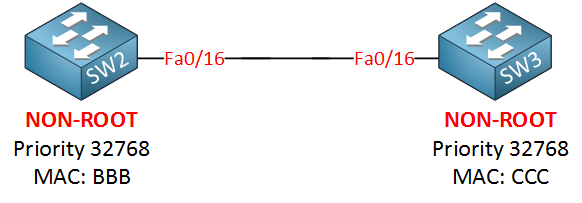
Let me show you the configuration by using SW2 and SW3, first I will make sure that SW3 is NOT the root bridge
SW2(config)#spanning-tree vlan 1 priority 4096
Now we’ll enable root guard on SW2:
					SW2(config)#interface fa0/16
SW2(config-if)#spanning-tree guard root
%SPANTREE-2-ROOTGUARD_CONFIG_CHANGE: Root guard enabled on port FastEthernet0/16.
We get a nice notification message that it has been enabled. Let’s enable a debug so we can see what is going on:
					SW2#debug spanning-tree events
Spanning Tree event debugging is on
					1. Make Switch Root Bridge (Primary)
Switch(config)# spanning-tree vlan 10 root primary

Automatically makes this switch Root Bridge for VLAN 10
Cisco adjusts priority automatically (lower value)


2. Make Switch Backup Root Bridge (Secondary)
Switch(config)# spanning-tree vlan 10 root secondary


3. Manually Set Root Bridge Priority
Switch(config)# spanning-tree vlan 10 priority 4096

Lower priority = higher chance to become Root Bridge
Default priority = 32768
Must be lower than other switches


4. Set Same Root for All VLANs (Multiple VLANs)
Switch(config)# spanning-tree vlan 1-100 root primary

Makes switch Root Bridge for multiple VLANs


5. Manual Root Bridge for Multiple VLANs (Priority Method)
Switch(config)# spanning-tree vlan 10,20,30 priority 4096

Manually forces Root Bridge selection


6. Verify Root Bridge
Switch# show spanning-tree

Shows:

Root Bridge ID
Local Bridge ID
Root Port
STP status

7. Show Root Bridge Only
Switch# show spanning-tree root

Displays current Root Bridge information

9. Important Notes
Lower priority = better chance to become Root
Root Bridge should be core/distribution switch
Only one Root Bridge per VLAN


10. Short Summary
Root Bridge commands:
spanning-tree vlan 10 root primary
spanning-tree vlan 10 root secondary
spanning-tree vlan 10 priority 4096
Enable Rapid PVST+ Mode
					Rapid PVST+ (Rapid Per VLAN Spanning Tree)
is a faster version of STP that gives quick convergence.


1. Enable Rapid PVST+ Mode (Main Command)
Switch(config)# spanning-tree mode rapid-pvst

Enables Rapid PVST for all VLANs
Faster convergence than classic STP

2. Verify STP Mode
Switch# show spanning-tree summary
Shows current mode (PVST / Rapid-PVST / MST)


3. Show Rapid PVST for VLAN
Switch# show spanning-tree vlan 10

Displays STP details for VLAN 10
Shows root, ports, roles

4. Can RSTP (Rapid PVST+) works on trunk ports in Spanning Tree Protocol?
Yes, Rapid PVST+ is fully supported on trunk ports.
You do NOT need any special “trunk RSTP command”.
Spanning Tree Protocol PortFast Commands
					PortFast is used on access ports to make the interface move immediately to forwarding
state without waiting for STP listening and learning timers.
1. Enable PortFast on Interface
Switch(config)# interface fa0/1
Switch(config-if)# spanning-tree portfast

Enables PortFast on Fa0/1

2. Global PortFast Configuration
Enable PortFast automatically on all access ports:
Switch(config)# spanning-tree portfast default

Applies PortFast globally to access ports

3. PortFast on Trunk Port (Special Case)
Switch(config)# interface g0/1
Switch(config-if)# spanning-tree portfast trunk

Used only in special environments like:
Server trunk
Router trunk
VMware/virtualization links

❌Not recommended for switch-to-switch trunk
STP Show Commands
					Basic STP Show Commands
.......................
1.Show Complete STP Information
Switch# show spanning-tree

Displays:

STP mode
Root bridge
Port roles
Port states
VLAN STP details

2.Show STP for Specific VLAN
Switch# show spanning-tree vlan 10


3.Show Root Bridge Information
Switch# show spanning-tree root

Shows:

Current root bridge
Root port
Root path cost

4.Show Blocked Ports
Switch# show spanning-tree blockedports

Displays all STP blocked interfaces.


Interface Related Commands
..........................
1.Show STP on Specific Interface
Switch# show spanning-tree interface fa0/1
Displays STP details for interface Fa0/1.

2.Show Interface BPDU Guard Status
Switch# show spanning-tree interface fa0/1 detail


Root Bridge Verification Commands
.................................
1.Show Root Port Details
Switch# show spanning-tree root
Shows which interface is acting as root port.

2.Show Bridge Priority
Switch# show spanning-tree bridge

Displays:

Bridge ID
Priority
MAC address


STP Mode Verification
.....................
1.Show Current STP Mode
Switch# show spanning-tree summary

Displays:

PVST/RPVST/MST mode
PortFast status
BPDU Guard status


STP Statistics Commands
.......................
Switch# show spanning-tree detail

Displays:

BPDU counters
Topology changes
Timers
Port transitions


Show Topology Change Information
................................
Switch# show spanning-tree detail | include ieee|occurr|from
Shows topology change history.


Rapid PVST Commands
...................
1.Show Rapid PVST Information
Switch# show spanning-tree summary
Displays Rapid PVST operation status.


EtherChannel STP Commands
.........................
1.Show STP with EtherChannel
Switch# show spanning-tree interface port-channel 1
Displays STP details for EtherChannel.


Cisco Useful Filtering Commands
...............................
1.Show Only Root Information
Switch# show spanning-tree | include Root
Filters only root-related lines.

2.Show Only Blocking Ports
Switch# show spanning-tree | include BLK
Displays forwarding ports only.

Common STP show commands:
Command	Purpose:
show spanning-tree	                    Full STP details
show spanning-tree vlan 10	            VLAN-specific STP
show spanning-tree root	Root bridge info
show spanning-tree blockedports	        Blocked ports
show spanning-tree summary	            STP summary
show spanning-tree detail	            Detailed counters
show spanning-tree interface fa0/1	    Interface STP status
Spanning Tree Protocol STP Debug Commands
					1. Debug STP Events
Switch# debug spanning-tree events

Shows:

Port state changes
STP transitions
Topology events


2. Debug BPDU Packets
Switch# debug spanning-tree packets\


Displays:

Sent BPDU
Received BPDU
BPDU type/details


3. Debug STP State Changes
Switch# debug spanning-tree switches

Shows:

STP role/state changes
Root election process

4. Debug Rapid PVST / RSTP
Switch# debug spanning-tree rstp events

Used for Rapid STP troubleshooting

5. Debug Topology Changes
Switch# debug spanning-tree topology-change

Detects:

TCN BPDU
Topology recalculation


6. Debug Interface STP Activity
Switch# debug spanning-tree interface fa0/1

Monitors STP events on specific interface


7. Disable All Debug
Switch# undebug all

Stops all active debugging


8. Verify Debug Status
Switch# show debugging

Shows currently active debug processes
Root Guard Configuration
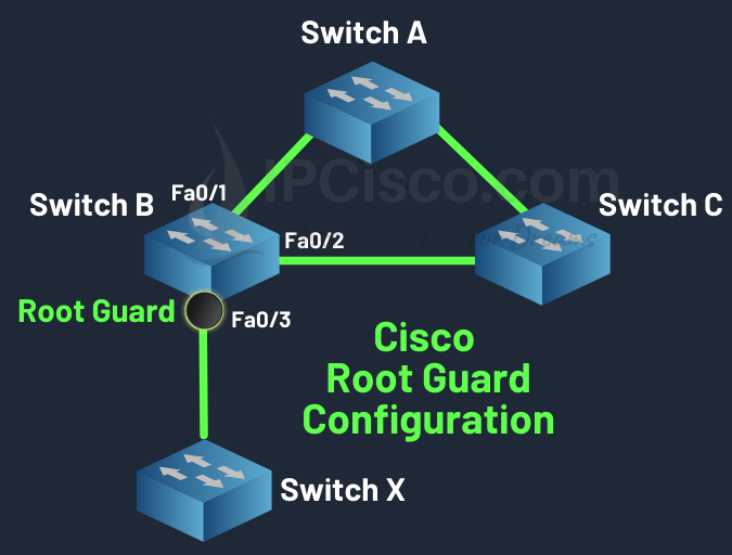
					Switch B# config terminal
Switch B(config)# interface fastethernet 0/3
Switch B(config-if)# spanning-tree guard root


How Root Guard Works?
When Root Guard is enabled on a port:

.The port normally forwards traffic
.If superior BPDU packets are received, the port moves to Root-Inconsistent State
.Traffic forwarding stops temporarily
.When superior BPDU packets stop, the port automatically recovers


.....Real Example Root Guard.....
Suppose:
Core Switch ----- Access Switch
The Core Switch should always remain Root Bridge.

If another switch is connected improperly:
Core Switch ----- Access Switch ----- New Switch

The New Switch may try to become Root Bridge.
Root Guard blocks this behavior.

Root Guard Configuration Command
.................................
Enable Root Guard on Interface
Switch(config)# interface fa0/1
Switch(config-if)# spanning-tree guard root

Meaning:
Enter interface mode
Enable Root Guard on Fa0/1

Verification Commands
.....................
Switch# show spanning-tree interface fa0/1 detail

Displays:

Root Guard status
Port role
STP state

Show Root-Inconsistent Ports
Switch# show spanning-tree inconsistentports
Shows ports blocked by Root Guard.
BPDU Guard Configuration
					Configuring BPDU Guard Globally at Global Configuration Mode
Commands to enable BPDU Guard by default on all PortFast Edge Ports :
.....................................................................

system#configure terminal
system(config)#spanning-tree portfast edge bpduguard default
system(config)#exit


Commands to disable BPDU Guard on all PortFast Edge Ports :
...........................................................

system#configure terminal
system(config)#no spanning-tree portfast edge bpduguard default
system(config)#exit
					Configuring BPDU Guard at Interface Configuration Mode per interface
Commands to enable BPDU Guard for an interface
....................................................................

system#configure terminal
system(config)#interface giga 0/0
system(config-if)#spanning-tree bpduguard enable
system(config-if)#exit
system(config)#exit


Commands to disable BPDU Guard for an interface
...............................................
system#configure terminal
system(config)#interface giga 0/0
system(config-if)#spanning-tree bpduguard disable
system(config-if)#exit
BPDU Filter Configuration
					1. Interface Level BPDU Filter Configuration
Enable BPDU Filter on a specific interface:
Switch(config)# interface fa0/1
Switch(config-if)# spanning-tree bpdufilter enable

Disable BPDU filtering
Switch(config-if)# spanning-tree bpdufilter disable


2. Global BPDU Filter Configuration (Recommended method)
Enable BPDU Filter globally on all PortFast ports:

Switch(config)# spanning-tree portfast bpdufilter default

Applies automatically to all PortFast-enabled interfaces
Safer than interface-level configuration

-----Disable Global BPDU Filter-----
Switch(config)# no spanning-tree portfast bpdufilter default

-----Check After Disable-----
Switch# show spanning-tree interface fa0/1 detail

-----Check STP status:-----
Switch# show spanning-tree summary


3. PortFast + BPDU Filter Global Example
Switch(config)# spanning-tree portfast default
Switch(config)# spanning-tree portfast bpdufilter default
Port Security Configuration With 5 Devices
					Sticky Port Security Configuration (Allow 5 Devices)
....................................................
1. Enter Interface Mode
Switch# configure terminal
Switch(config)# interface fastEthernet 0/1


2. Set Port as Access Port and Enable Port Security
Switch(config-if)# switchport mode access
Switch(config-if)# switchport port-security

3. Set Maximum 5 Devices
Switch(config-if)# switchport port-security maximum 5

4. Enable Sticky MAC Learning
Switch(config-if)# switchport port-security mac-address sticky

5. Set Violation Mode (Example: Shutdown)
Switch(config-if)# switchport port-security violation shutdown

6. Save Configuration
Switch# write memory


Manual Port Security Configuration (5 Devices)
..............................................

1. Enter Interface Mode
Switch# configure terminal
Switch(config)# interface fastEthernet 0/1


2. Set Port as Access Port and Enable Port Security
Switch(config-if)# switchport mode access
Switch(config-if)# switchport port-security

3. Set Maximum 5 Devices
Switch(config-if)# switchport port-security maximum 5

4. Manually Add Allowed MAC Addresses (5 Devices)
Switch(config-if)# switchport port-security mac-address 00:11:22:33:44:01
Switch(config-if)# switchport port-security mac-address 00:11:22:33:44:02
Switch(config-if)# switchport port-security mac-address 00:11:22:33:44:03
Switch(config-if)# switchport port-security mac-address 00:11:22:33:44:04
Switch(config-if)# switchport port-security mac-address 00:11:22:33:44:05

5. Set Violation Mode (Example: Shutdown)
Switch(config-if)# switchport port-security violation shutdown

6. Save Configuration
Switch# write memory

Port Security Show Commands
...........................
1. Check Port Security Status (All Interfaces)
show port-security

2. Check Specific Interface Status
show port-security interface fastEthernet 0/1

3. Show Secure MAC Addresses
show port-security address

4. Show Running Configuration
show running-config

5. Show MAC Address Table (Helpful)
show mac address-table

6. Check Disabled Port Status
show interface status

7. Manually Recover (Reset Port)
configure terminal
interface fastEthernet 0/1
shutdown
no shutdown