MLAG Technology
What is Switching MLAG
MLAG (Multi-Chassis Link Aggregation) is a network technology that allows a device (such as a server, access switch, or firewall) to create one logical EtherChannel (link aggregation group) using physical links connected to two different switches at the same time. Normally, EtherChannel works only between two single devices, but MLAG makes two switches behave like one logical switch for that connection. This design removes the single point of failure and provides both high availability and increased bandwidth.
In an MLAG setup, the two switches are called MLAG peers. They are connected with a special high-speed link known as a peer link, which is used to synchronize control information such as MAC addresses, VLANs, ARP tables, and link status. The peers also use a keepalive link to detect if the other switch is alive. From the connected device’s perspective, it sees only one EtherChannel and does not know that it is connected to two separate switches. Because both links are active and forwarding at the same time, Spanning Tree Protocol (STP) does not block any link, which improves bandwidth usage and reduces network convergence time.
The main benefits of MLAG are redundancy, fast failover, and full utilization of links. If one switch fails or one link goes down, traffic automatically continues through the remaining switch with almost no interruption. This makes MLAG very popular in data centers and enterprise networks for connecting servers, storage systems, firewalls, and access switches to distribution or core switches. Different vendors use different names for MLAG technology, such as vPC (Cisco), IRF (HPE), or VLT (Dell), but the working principle is the same.
In simple words, MLAG allows one device to connect to two switches as if they were one, giving you no single point of failure, higher bandwidth, and more stable network performance compared to normal EtherChannel.
After a two-switch MLAG (Multi-Chassis Link Aggregation) setup, the control plane traffic is synchronized between both switches so that they can behave like one logical switch for connected devices. Each switch still runs its own control plane processes (such as MAC learning, ARP/ND tables, LACP, VLAN information, and sometimes routing), but these details are continuously exchanged over a special link called the peer link and monitored through a keepalive link. This synchronization ensures that both switches have the same network state information, so traffic forwarding remains consistent and stable.
In MLAG, when one switch learns a MAC address or receives ARP information from a connected device, it shares this control plane information with the peer switch through the peer link. The same happens for LACP status, VLAN membership, and port state. Because of this, both switches know which device is connected and how to forward frames, even though the device is physically connected to only one of them. If one switch fails, the other switch already has the required control plane data and can immediately take over forwarding without waiting for long reconvergence. This is why MLAG provides fast failover and avoids Spanning Tree blocking.
In simple terms, after MLAG is configured, control plane traffic is mirrored and synchronized between the two switches, but each switch still keeps its own control plane. They are not merged into one CPU; instead, they act as two independent switches that constantly exchange control information so that forwarding decisions stay the same on both sides. This shared control plane state is what allows MLAG to provide high availability, no single point of failure, and seamless traffic forwarding.
Key Concepts of MLAG:
- Redundancy: MLAG ensures that if one physical link or switch fails, the other one can take over, providing uninterrupted network services.
- Load Balancing: By combining multiple links, MLAG enables better distribution of network traffic, optimizing the use of available bandwidth.
- Multiple Chassis: In MLAG, two switches are involved. One acts as the primary and the other as the secondary switch. They appear as a single device to end devices or upstream switches.
- Loop Prevention: Protocols like the Spanning Tree Protocol (STP) or MLAG-specific protocols help in preventing network loops while allowing the redundancy and increased bandwidth benefits of MLAG.
Benefits of MLAG:
- High Availability: If one switch fails, the other can still forward traffic without interruption, ensuring network uptime.
- Better Utilization of Links: MLAG allows you to maximize the use of available bandwidth between devices by aggregating multiple links.
- Scalability: More links can be added to increase capacity, making the network scalable to meet increasing demand.
Example Use Case:
In a data center, MLAG could be used to connect two aggregation switches to multiple server racks. The servers would each connect to both aggregation switches through two separate physical links (configured as part of an EtherChannel). If one of the aggregation switches fails, the traffic can continue to flow through the other switch, ensuring network reliability.
Would you like more details on how MLAG works in practice with a specific vendor’s equipment?
Normal EtherChannel and Multi-Chassis EtherChannel
Normal EtherChannel and Multi-Chassis EtherChannel (MLAG / MC-LAG) both bundle multiple physical links into one logical link to increase bandwidth and provide redundancy, but the key difference is how many switches are involved and the level of high availability they provide.
In a normal EtherChannel, all the bundled links connect between the same two devices (for example, one access switch connected to one distribution switch). The EtherChannel is formed only with a single switch on each side, so if that switch fails, the entire connection goes down even though multiple links were bundled. Normal EtherChannel works with protocols like LACP or PAgP and still depends on Spanning Tree Protocol (STP) to avoid loops when multiple switches are involved. It mainly provides link-level redundancy and higher bandwidth, but not switch-level redundancy.
In contrast, Multi-Chassis EtherChannel (MLAG) allows one device (such as a server or access switch) to form a single logical EtherChannel with two different physical switches at the same time. These two switches act as one logical unit using a special peer link and synchronization mechanism. This design provides both link redundancy and switch redundancy. If one switch fails, traffic automatically continues through the other switch with almost no interruption. MLAG also allows all links to be active and forwarding simultaneously, so STP does not block one of the links, giving better bandwidth utilization and higher availability.
Key Differences
| Feature | Normal EtherChannel | Multi-Chassis EtherChannel (MLAG) |
|---|---|---|
| Number of switches | One switch on each side | Two switches act as one logical switch |
| Redundancy type | Link redundancy only | Link + switch redundancy |
| Switch failure impact | Connection fails if switch fails | Traffic continues via other switch |
| STP behavior | STP may block links in some designs | STP not required on MLAG links |
| Complexity | Simple to configure | More complex (peer link, sync required) |
| Use case | Basic uplinks between switches | Data centers, servers, firewalls, core networks |
In simple terms, normal EtherChannel = multiple links between two single switches, while Multi-Chassis EtherChannel = multiple links spread across two switches working together as one, giving much higher reliability and no single point of failure.
Benefits Of MLAG in Company Network
MLAG (Multi-Chassis Link Aggregation) is very important in a company network because it provides high availability, redundancy, and better bandwidth utilization. With MLAG, a server, firewall, or access switch can connect to two different switches at the same time as one logical link. This removes the single point of failure in the network. If one switch fails or one uplink cable is cut, traffic automatically continues through the other switch without network downtime. MLAG also allows all links to remain active and forwarding, so the company gets full use of available bandwidth instead of having one link blocked by Spanning Tree Protocol (STP). This results in faster performance, stable connectivity, and minimal service interruption for critical applications like email, ERP systems, cloud services, and VoIP.
Without MLAG in a company network, several serious problems can occur. Normally, a device connects to only one switch or uses a normal EtherChannel to a single switch, so if that switch fails, the entire connection goes down and users lose network access. In traditional designs without MLAG, STP blocks one of the redundant links to prevent loops, which wastes bandwidth and slows down failover when a link or switch fails. This can cause noticeable downtime, packet loss, and application disconnections. For servers and data centers, this means business services may stop completely until the failed switch is restored. In short, without MLAG, company networks suffer from single points of failure, unused backup links, slower recovery during failures, and lower overall reliability, which can directly impact productivity and business operations.
In simple words:
- With MLAG: high availability, no downtime, full bandwidth, stable network.
- Without MLAG: risk of switch failure, blocked links by STP, downtime, and poor network performance.


In the era of digital transformation, data centers have become the cornerstone of enterprise operations, enabling everything from cloud computing to big data analytics. As businesses expand and their network traffic grows exponentially, ensuring high availability, scalability, and operational efficiency within data centers is more critical than ever. Multi-Chassis Link Aggregation Group (MLAG) has emerged as a pivotal technology to address these needs, providing robust solutions for network redundancy, load balancing, and simplified management. This article will delve into the fundamental concepts of MLAG, explore its diverse applications, and discuss its crucial role in modern data center network design.
MLAG Overview
Multi-Chassis Link Aggregation Group (MLAG) is a sophisticated networking technology that enhances traditional Link Aggregation Group (LAG) by allowing link aggregation across multiple switches. This architecture significantly improves network performance and reliability by providing enhanced redundancy and load balancing.
MLAG functions by presenting two or more physical switches as a single logical switch to connected devices. This is made possible through synchronization protocols and control mechanisms that ensure coordinated operation of the switches. Key components of MLAG include:
Control Plane Synchronization: Ensures that MLAG peers maintain consistent forwarding states and configurations.
Data Plane Operations: Facilitates efficient data transfer across aggregated links, balancing the load and ensuring seamless failover capabilities.
Keep Alive Mechanisms: Monitors the health of MLAG peers, detecting failures and triggering appropriate responses to maintain network stability.

Is MLAG the Same as LACP?
While MLAG (Multi-Chassis Link Aggregation Group) and LACP (Link Aggregation Control Protocol) both aim to enhance network performance and reliability through link aggregation, they are not the same. They differ in their scope, operation, and use cases. Here’s a comparison to highlight their distinctions:
Scope and Operation
MLAG:
- Scope: Operates across multiple switches, treating them as a single logical switch to connected devices.
- Redundancy: Provides high redundancy by allowing failover between switches.
- Load Balancing: Distributes traffic across multiple switches.
- Management Complexity: Requires more complex configuration and synchronization between multiple switches.
- Scalability: More scalable for large networks, accommodating growing demands with multiple switches.
LACP:
- Scope: Operates within a single switch, bundling multiple physical links into a single logical link.
- Redundancy: Provides redundancy within a single switch, allowing traffic rerouting if a link fails.
- Load Balancing: Distributes traffic across multiple links within the same switch.
- Management Complexity: Simpler to configure and manage due to its operation within a single switch and adherence to the IEEE 802.3ad standard.
- Scalability: Limited to the link aggregation capabilities of a single switch, less scalable for extensive networks.
Key Differences
- Operation: MLAG spans multiple switches, while LACP is confined to a single switch.
- Redundancy and Failover: MLAG offers switch-level redundancy, whereas LACP provides link-level redundancy within one switch.
- Complexity: MLAG involves more complex setup and synchronization, while LACP is easier to implement and manage due to its standardization.
- Use Cases: MLAG is suitable for large, scalable, and highly available network environments. LACP is ideal for simpler setups requiring link aggregation within a single switch.
Summary Table
Feature | MLAG | LACP |
Scope of Operation | Multiple switches | Single switch |
Redundancy | High (failover between switches) | Moderate (failover within switch) |
Load Balancing | Across multiple switches | Across multiple links in one switch |
Management Complexity | Higher (involves multiple switches) | Lower (standardized protocol, single switch) |
Scalability | High (suitable for larger, scalable networks) | Lower (limited to single switch) |
Protocol Standards | Vendor-specific implementations | IEEE 802.3ad standard |
Failover Mechanism | Switch-level failover | Link-level failover |
What is MLAG Used for?
Spine-Leaf Architecture
In spine-leaf network topologies, MLAG is used to connect leaf switches to spine switches. This architecture ensures that traffic between any two devices in the data center can traverse multiple paths, enhancing fault tolerance and load distribution.
- High Throughput: Supports low-latency, high-throughput connections essential for data-intensive applications.
- Resilience: Multiple paths between devices improve fault tolerance and reliability.
Server Connectivity
MLAG is often used to dual-home servers to multiple switches, providing redundancy and higher aggregate bandwidth. This configuration is particularly beneficial for critical servers hosting applications that require high availability and consistent performance.
- Dual-Homing: Ensures servers remain connected even if one switch fails.
- Increased Bandwidth: Aggregates links to provide higher bandwidth to servers.
Storage Networks
In storage area networks (SANs), MLAG connects storage devices to multiple switches, ensuring that data access is not disrupted in case of a switch failure. This setup is vital for maintaining the integrity and availability of storage resources.
- Data Integrity: Continuous access to storage devices ensures data integrity.
- Availability: Maintains high availability of storage resources.
Disaster Recovery and Business Continuity
MLAG supports robust disaster recovery and business continuity solutions by providing geographically dispersed redundancy. By extending MLAG configurations across data centers in different locations, businesses can ensure that their critical applications remain operational even in the event of a site-level failure.
- Geographic Redundancy: Ensures network resilience across different geographic locations.
- Operational Continuity: Maintains critical services and applications during disasters.
MLAG vs. Stacking vs. LACP
Link aggregation and stacking are common approaches to bundle multiple network connections in one logical link. Compared to conventional connections, these methods are best described as scalable solutions that can provide higher availability, higher reliability and higher bandwidth. MLAG vs. stacking vs. LACP is often asked to define the differences, so this article intends to give an informed explanation of MLAG, LACP, stacking, and the different application scenarios.
Understanding MLAG, LACP, and Stacking
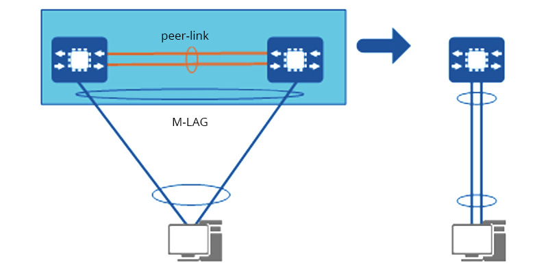
MLAG (Multi-chassis Link Aggregation Group): a non-standard protocol, that implements link aggregation among multiple devices. The devices at both ends of the MLAG send MLAG negotiation packets through the peer-link. The main purpose of MLAG is to deliver system-level redundancy in the event one of the chassis fails.
LACP (Link Aggregation Control Protocol): a subcomponent of IEEE 802.3ad standard, provides a method to control the bundling of several physical ports together to form a single logical channel. LACP allows a network device to negotiate an automatic bundling of links by sending LACP packets to the peer. For more basics, Understanding Link Aggregation Control Protocol will give you the answer.

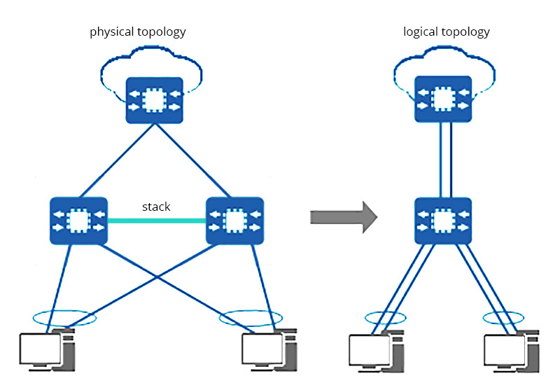
Stacking: a technology that enables multiple stacking-capable switches to function as a single logical switch. Stack link is connected by stacking cables to form a stack that connects all the switches in a specific topology. The stacking topology also defines the resiliency of the stacked solution. You can have typically different kinds of cabling options, depending on the switch vendor and models.

What is Switch Stacking?
A switch stack in networking is a configuration of multiple stackable switches connected via stacking cable and virtualized as a logically single device for data forwarding. It is a scalable solution to expand network capacity while not having trouble managing multiple physical devices. Also, adding or removing a switch in the stack won’t affect the stack system’s performance. Once one link or switch in the stacked switch unit fails, the stack system can continue to transfer data.
Some mainstream brands have slightly different names for this function, such as “Cisco StackWise”, “Aruba VSF”, and “Huawei istack”. Cisco even set terms to define various Cisco switch stacking versions. For example, Cisco’s StackWise technology supports a maximum of 8 stacks, and StackPower supports a maximum of 4 stacks.
What is MLAG?
MLAG (Multi-chassis Link Aggregation Group or Multi-chassis LAG) is a method to form the link aggregation group (LAG) among multiple devices for redundancy — When one of the switches fails, the system can still work. Though the IEEE 802.1AX-2008 standard that defined LAG does not mention Multi-chassis LAG, MLAG has become a widely applied link aggregation approach. It adds node-level redundancy to the legacy link-level redundancy that LAG provides.
The implementation of MLAG is proprietary, which means MLAG cannot be configured between switches of different vendors. Simply put, the mechanism is to connect two switches via peer-link and form a link aggregation group to act as a logically single device. More switches can be added to the link aggregation group using MLAG. MLAG topology can largely scale network capability, boost system reliability, and simplify management.
What is LACP?
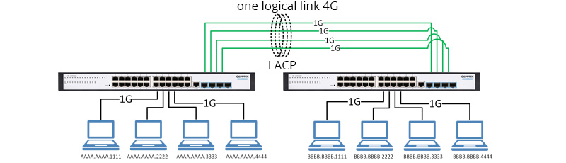
LACP (Link Aggregation Control Protocol), based on IEEE 802.3 ad standard, is a protocol that provides a method to realize dynamic link aggregation and de-aggregation. IEEE 802.3 ad LACP is to allow devices to automatically form link aggregation and perform data forwarding according to their own configuration. LACP aggregates multiple physical links into a logically single link, increases the network bandwidth, and delivers link redundancy. Four 1G link is a virtual 4G link. In the event one physical link fails, the other link in the LACP group will balance the load.
All QSFPTEK switches are LACP switches.