
Wiring Diagram
What is Biometric Connection Diagram
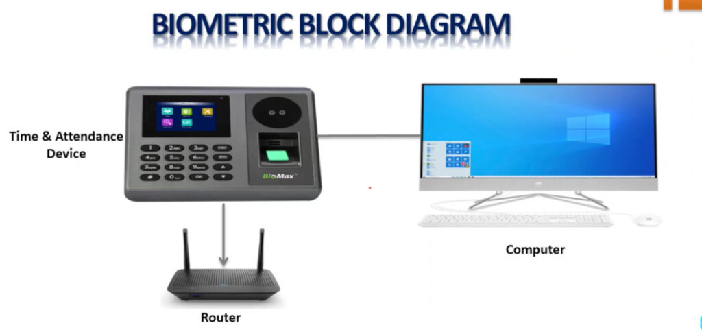
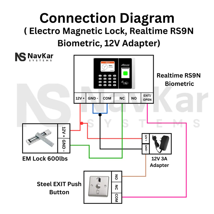
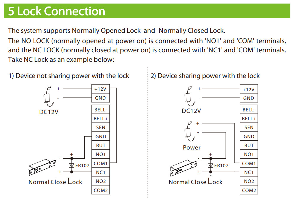
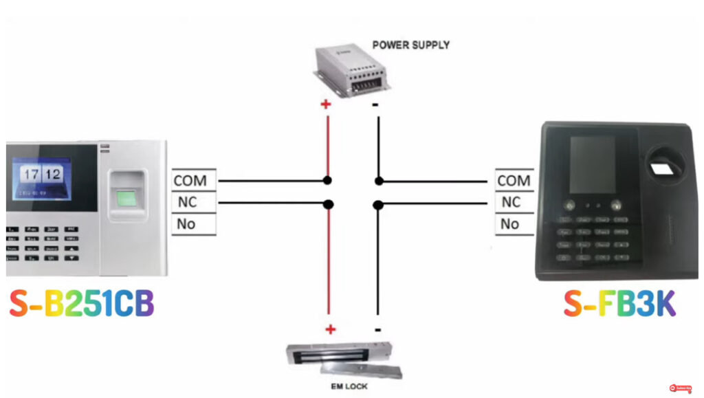
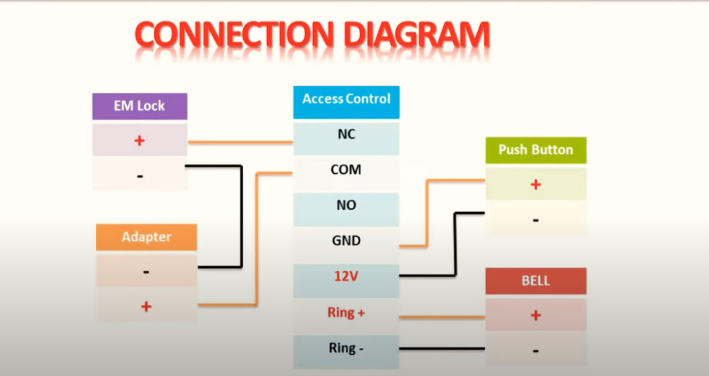
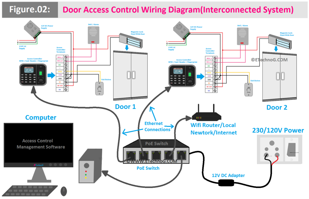
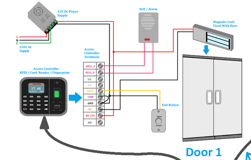
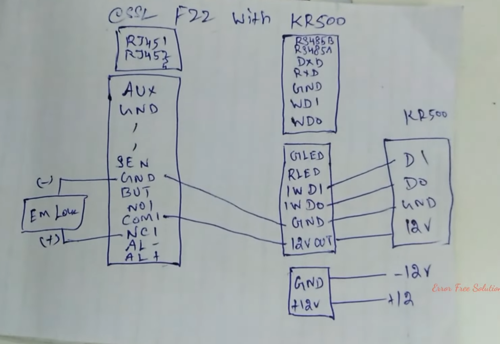
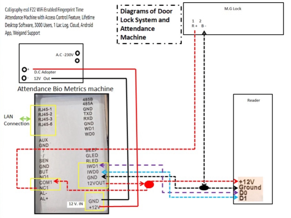
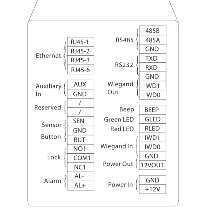
A Biometric Connection Diagram is a wiring schematic that shows how a biometric attendance or access control device is physically connected to all external components such as the power supply, network, door lock, exit button, door sensor, alarm, and communication interfaces. The purpose of the diagram is to provide technicians and installers with a clear visual representation of every electrical connection required for proper installation and operation. A complete biometric connection diagram helps prevent wiring mistakes, simplifies troubleshooting, and ensures that all components communicate correctly with the biometric controller.
A typical biometric connection diagram includes the following connections:
- Power Supply (+12V & GND): Supplies regulated 12V DC power to the biometric device from an adapter or access control SMPS.
- Ethernet (RJ45): Connects the biometric device to a network switch or router for communication with attendance or access control software.
- Relay Output (NO, COM, NC): Controls an electric strike lock or electromagnetic lock by switching the external power supplied to the lock.
- Exit Button (BUT & GND): Allows users to unlock the door from inside without authentication.
- Door Sensor (SEN & GND): Detects whether the door is open or closed and reports door status to the controller.
- Alarm Output (AL+ & AL−): Connects to an external siren or buzzer that activates during security events such as forced entry or door held open.
- Auxiliary Input (AUX & GND): Accepts signals from external devices such as fire alarm panels, emergency switches, or panic buttons to trigger predefined actions.
- RS485 (485A, 485B, GND): Provides long-distance serial communication with external readers, controllers, or management systems.
- RS232 (TXD, RXD, GND): Used for direct serial communication, configuration, or maintenance of the device.
- Wiegand Input (IWD0, IWD1, GND): Connects an external card reader or keypad to the biometric controller.
- Wiegand Output (WD0, WD1): Sends card or fingerprint credential data to another access controller.
- LED and Buzzer Control (GLED, RLED, BEEP): Operates external status LEDs and buzzers to indicate successful access, denied access, or alarm conditions.
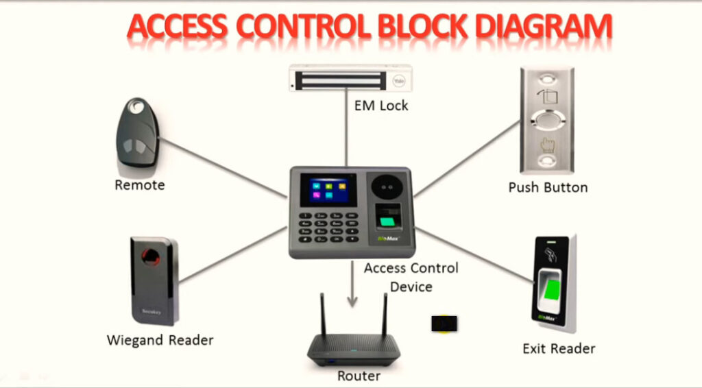
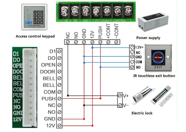
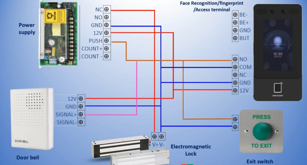
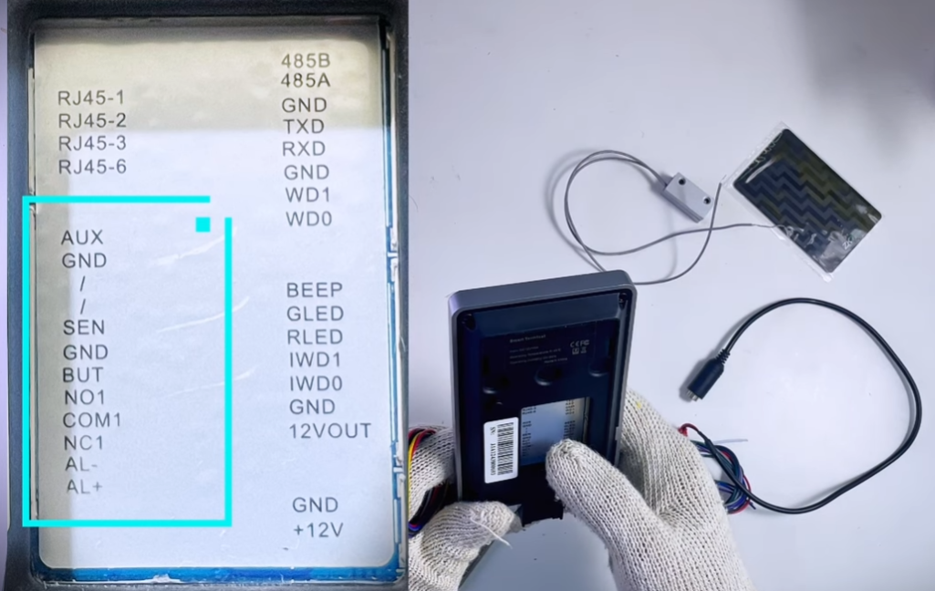
1. Power Input (+12V & GND)
The +12V and GND terminals are the primary power input connections of the biometric access control device. These terminals supply the required DC voltage to operate the internal processor, fingerprint sensor, RFID card reader, communication interfaces, relay module, and all internal electronic circuits. A regulated 12V DC power supply is recommended to ensure stable operation and prevent unexpected device restarts or hardware damage. The positive wire from the power adapter or access control power supply should be connected to the +12V terminal, while the negative wire should be connected to the GND terminal. For professional installations, a centralized access control SMPS with battery backup is recommended to maintain operation during power failures. Incorrect voltage or reverse polarity may permanently damage the device.
2. 12VOUT (Power Output)
The 12VOUT terminal provides a low-current 12V DC output for powering compatible external accessories such as card readers, door sensors, indicator LEDs, or small relay modules. This output is intended only for low-power devices and should not be used to power magnetic locks, electric strikes, sirens, or other high-current equipment. Exceeding the maximum output current may overload the internal power circuit and reduce the reliability of the biometric device. When installing high-power accessories, always use a separate regulated power supply.
3. Ethernet (RJ45)
The RJ45 Ethernet interface enables TCP/IP communication between the biometric device and the attendance or access control management software. Through the network connection, administrators can configure the device, synchronize users and fingerprints, download attendance records, monitor access events in real time, and perform firmware upgrades. The Ethernet interface supports integration into both local area networks (LAN) and wide area networks (WAN) using appropriate routing and firewall configurations. Proper IP address, subnet mask, gateway, and communication port configuration are essential for reliable communication.
4. AUX Input (AUX & GND)
The Auxiliary Input (AUX) terminal allows the biometric controller to receive signals from external devices such as emergency switches, fire alarm panels, panic buttons, motion sensors, or programmable automation systems. When the AUX input is activated, the device can execute predefined actions such as unlocking the door, activating an alarm, generating an event log, or sending notifications to the management software. The exact function depends on the access control configuration programmed within the device.
5. Door Sensor (SEN & GND)
The Door Sensor terminals monitor the physical status of the protected door. By connecting a magnetic door contact sensor, the biometric device can determine whether the door is open or closed. This information is used to detect events such as Door Forced Open, Door Held Open, or unauthorized access attempts. Both Normally Open (NO) and Normally Closed (NC) sensors may be supported depending on software configuration. Door monitoring improves the security and audit capabilities of the access control system.
6. Exit Button (BUT & GND)
The BUT (Exit Button) input allows users to unlock the door from inside the secured area without presenting a fingerprint or access card. Pressing the exit button momentarily shorts the BUT and GND terminals, signaling the biometric controller to activate the door relay. This method provides safe and convenient egress while maintaining secure entry authentication. Exit buttons are commonly installed near the inside of access-controlled doors.
7. Relay Output (NO1, COM1, NC1)
The Relay Output terminals are responsible for controlling external locking devices such as magnetic locks and electric strike locks. These terminals provide a Dry Contact Relay, meaning they do not supply voltage themselves but act as an electrically isolated switch. The COM (Common) terminal is connected internally to either NO (Normally Open) or NC (Normally Closed) depending on the relay state. Magnetic locks typically use the NC contact, while electric strikes commonly use the NO contact. Proper wiring ensures reliable and secure door control.
8. Alarm Output (AL+ & AL−)
The Alarm Output terminals are designed to activate external alarm devices such as sirens, buzzers, warning lights, or notification systems. Alarm events may include forced door opening, door held open beyond the allowed time, tamper detection, multiple invalid authentication attempts, or emergency conditions. Depending on the device model, the alarm output may provide a voltage signal or operate as a switching output requiring an external relay. Proper configuration allows the alarm system to respond automatically to security events.
9. RS485 Communication (485A, 485B, GND)
The RS485 communication interface provides reliable long-distance serial communication between the biometric device and external equipment. Typical applications include connecting additional fingerprint readers, access controllers, elevator controllers, or centralized management systems. RS485 supports communication distances of up to approximately 1200 meters under suitable conditions. The communication lines are normally labeled 485A (D+) and 485B (D−). Proper cable polarity and termination improve communication stability.
10. RS232 Communication (TXD, RXD, GND)
The RS232 interface is a traditional serial communication port used for direct communication with computers or embedded controllers. Although largely replaced by Ethernet and RS485, RS232 remains useful for device configuration, firmware recovery, diagnostics, and compatibility with legacy systems. Because RS232 is designed for short-distance communication, cable lengths are generally limited to approximately 15 meters.
11. Wiegand Output (WD0 & WD1)
The Wiegand Output interface transmits credential information such as card numbers or authentication data to an external access controller. When a valid card or fingerprint is presented, the biometric device outputs the credential using the standard Wiegand protocol. This allows the biometric terminal to function as a reader within larger access control systems managed by third-party controllers.
12. Wiegand Input (IWD0, IWD1 & GND)
The Wiegand Input interface allows connection of an external card reader or keypad. The external reader sends credential information to the biometric controller, enabling secure two-door or indoor/outdoor reader configurations. Wiegand input is commonly used when a separate outdoor card reader is required while keeping the biometric controller protected inside the building.
13. BEEP
The BEEP terminal controls an external buzzer or audible notification device. It can generate sound indications for successful authentication, access denial, alarm conditions, or system notifications. External buzzers improve user feedback and help operators recognize security events without constantly monitoring the software interface.
14. GLED (Green LED)
The Green LED Control output is used to operate an external green indicator LED. The LED typically illuminates when access is granted or when the door unlocks successfully. External status indicators improve user experience by providing clear visual confirmation of successful authentication.
15. RLED (Red LED)
The Red LED Control output operates an external red indicator LED. The LED is commonly used to indicate access denial, authentication failure, communication errors, or alarm conditions. Together with the green LED and buzzer, it provides immediate visual feedback regarding the operational status of the access control system.