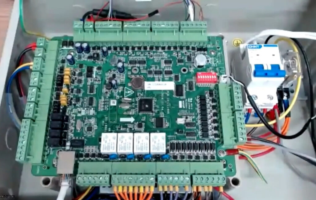
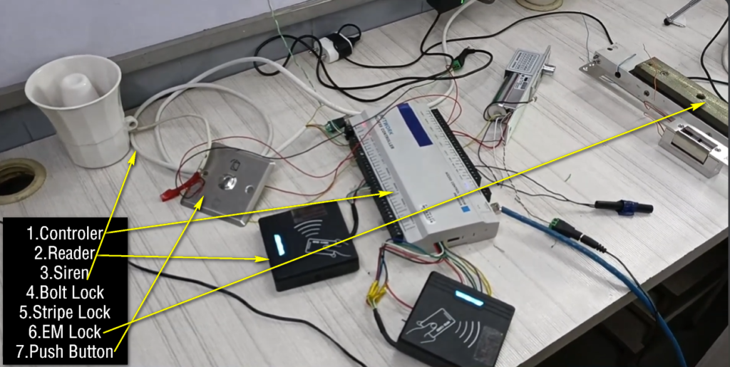
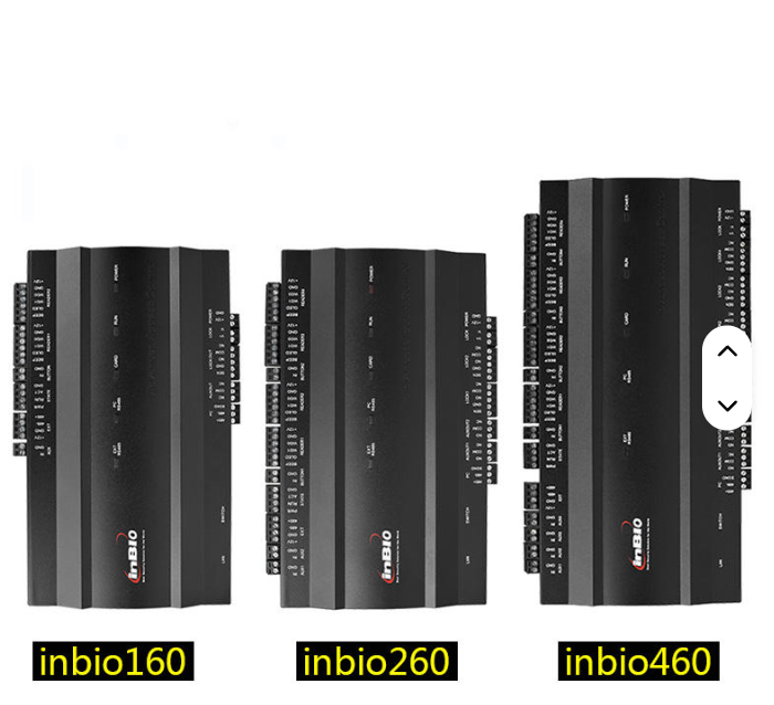
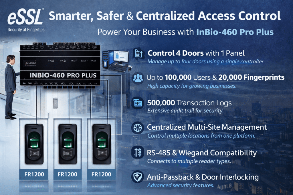
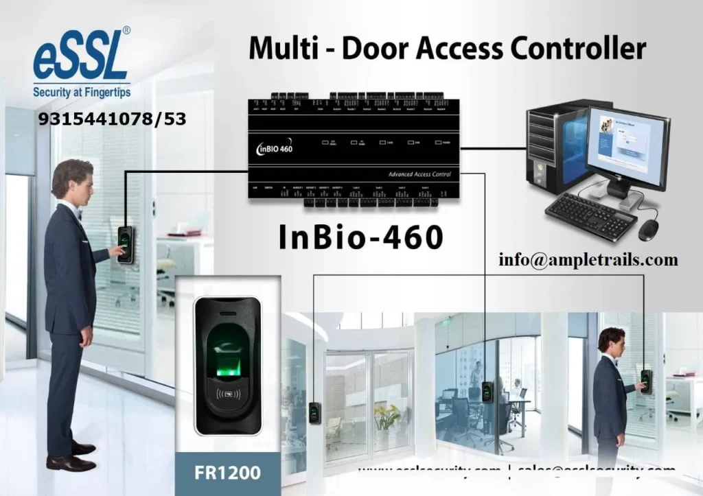
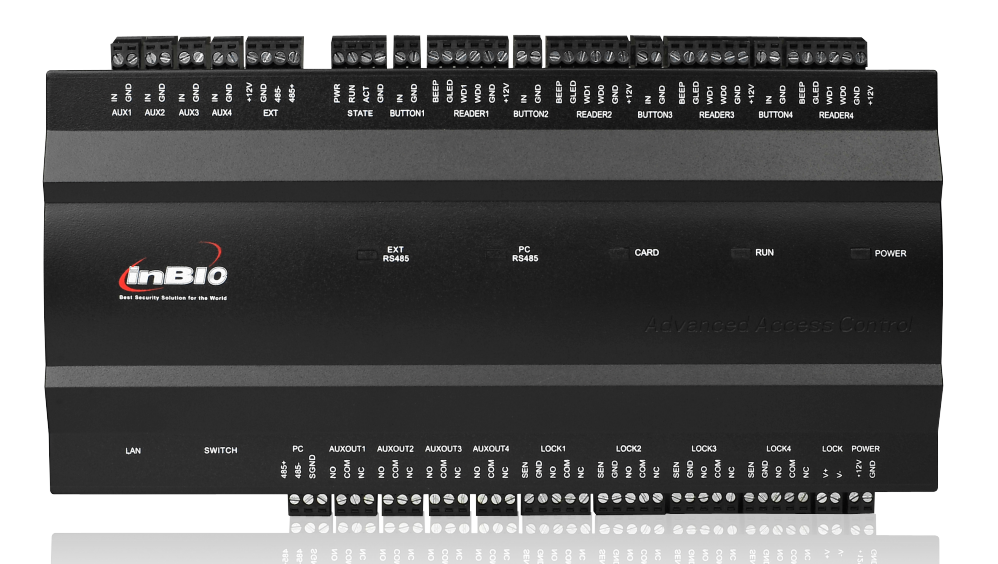
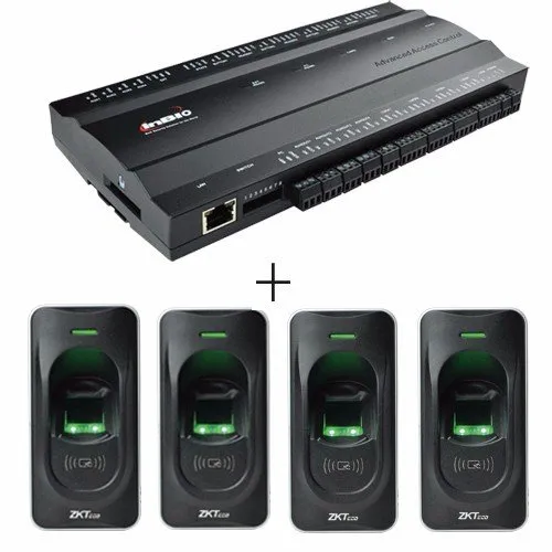
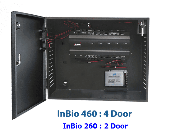
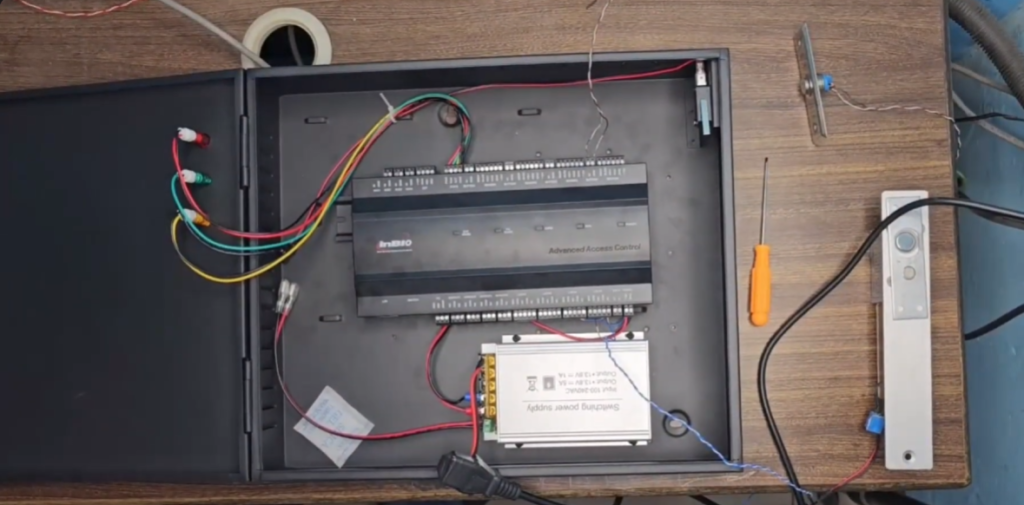
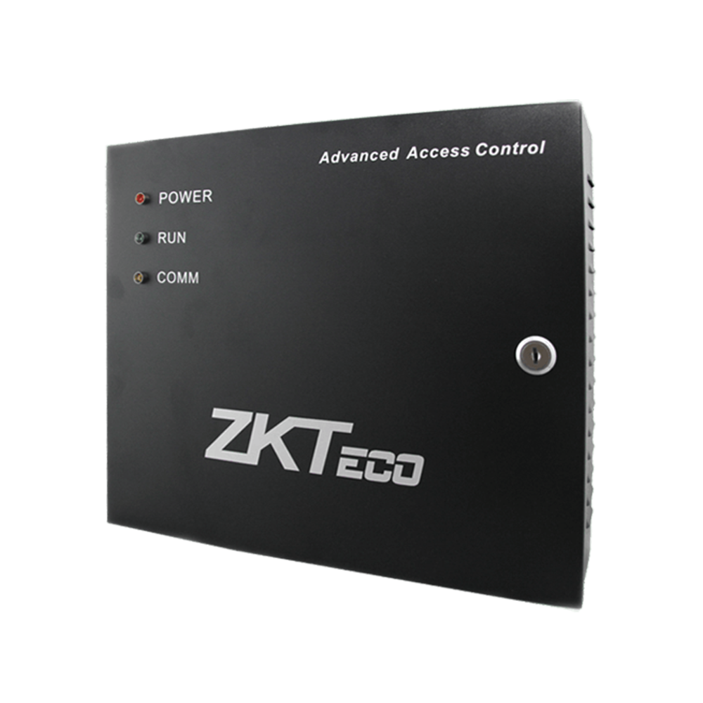
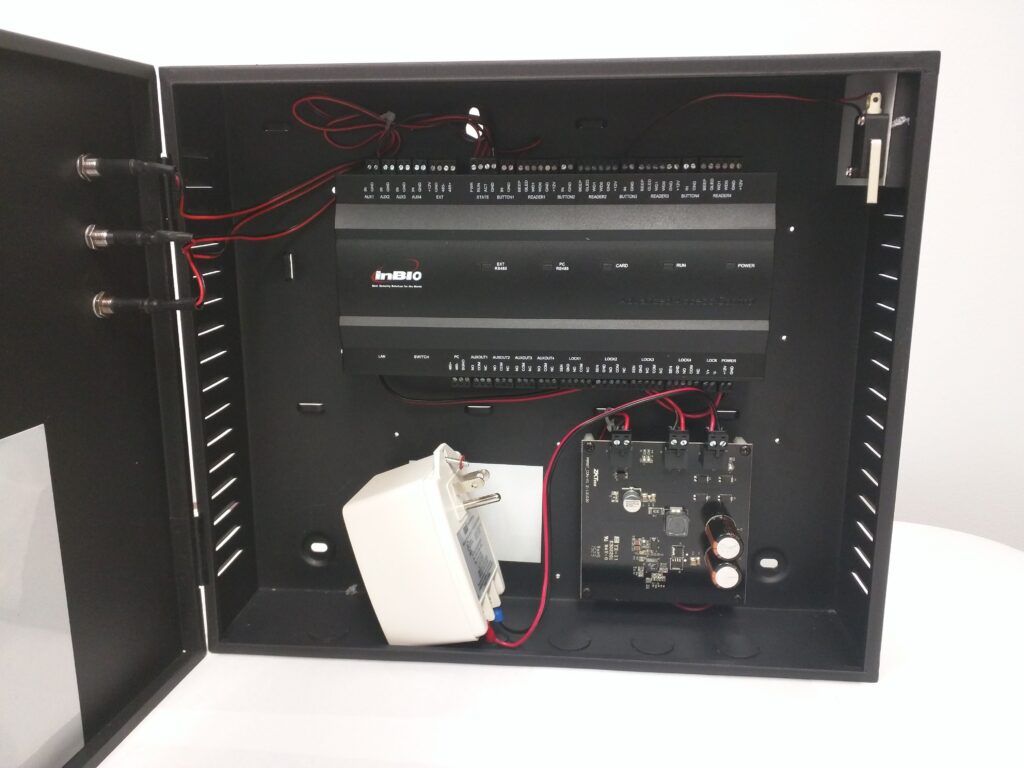
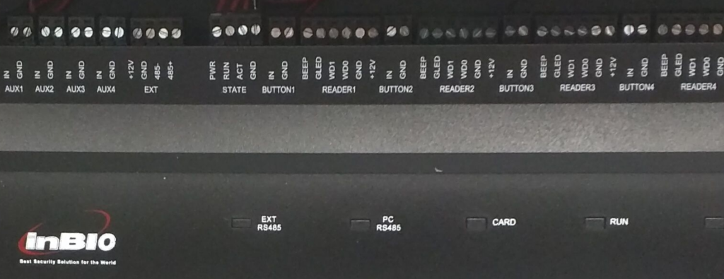
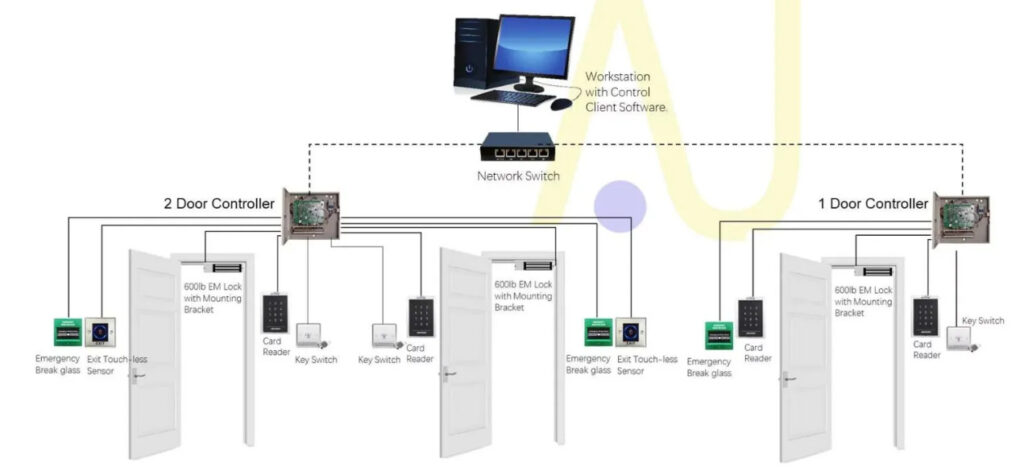
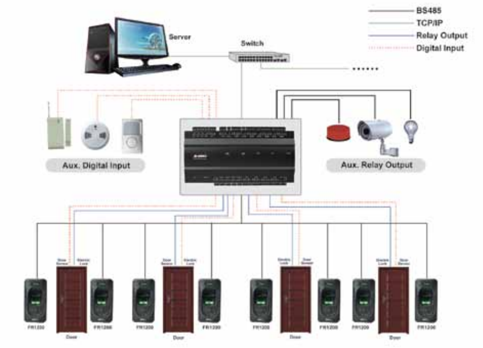
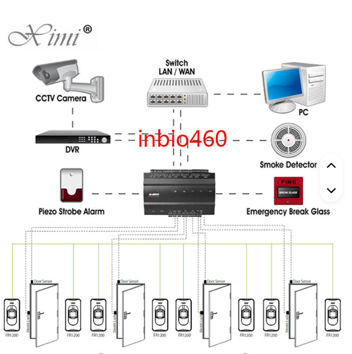
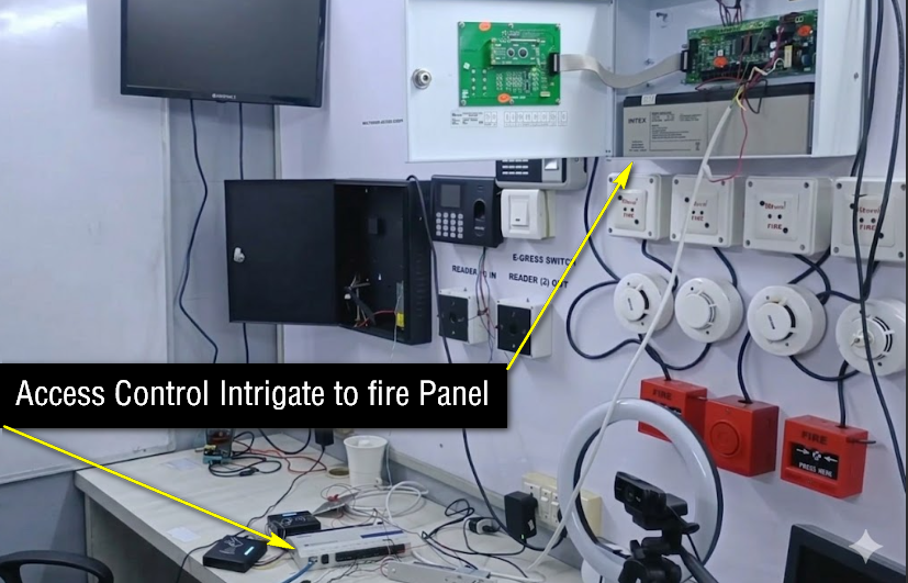
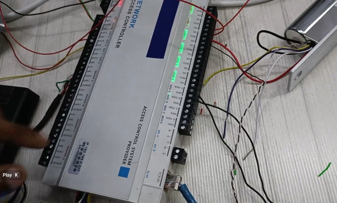
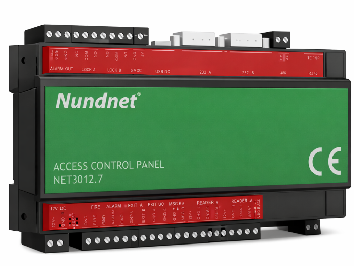
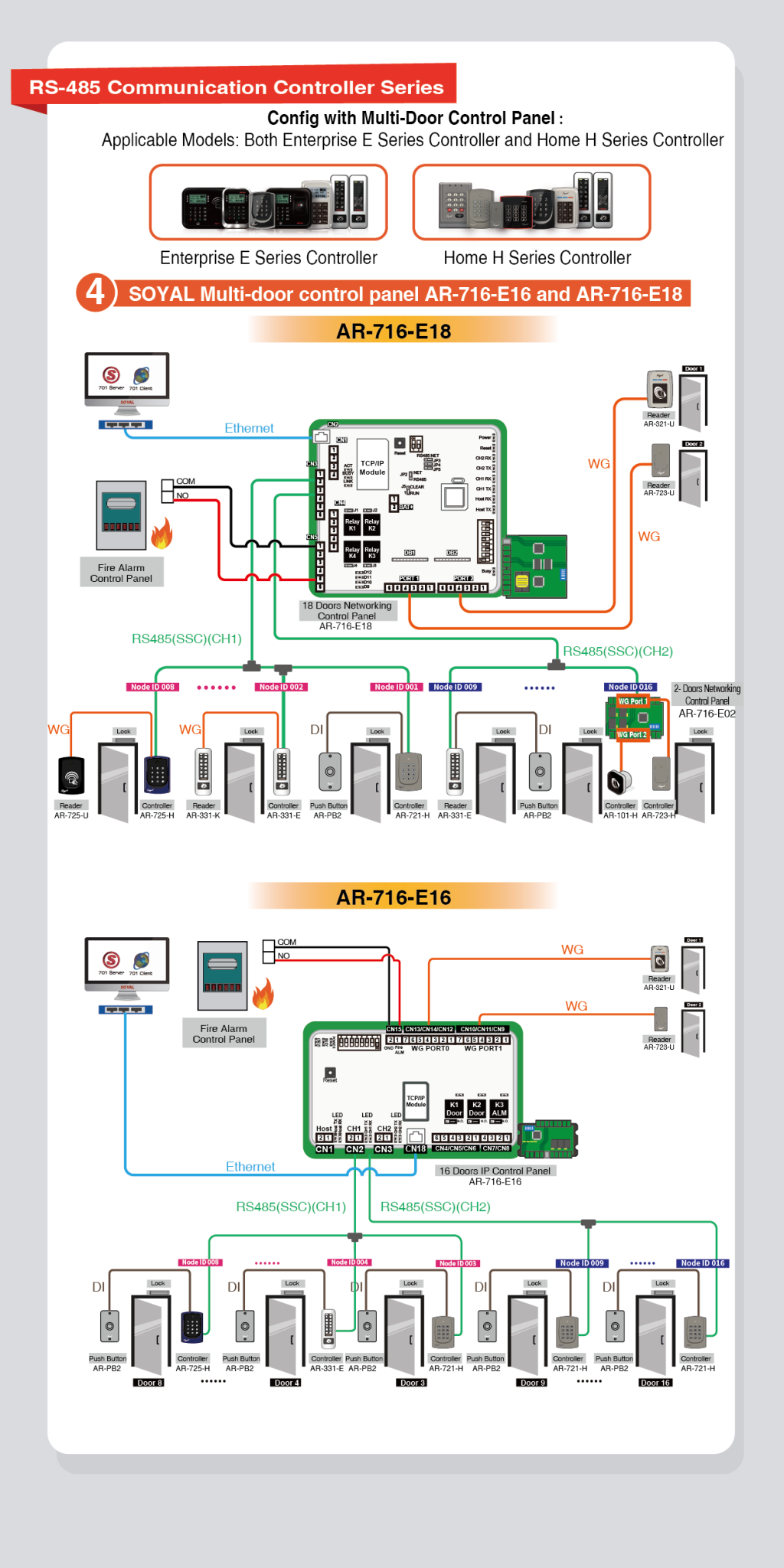
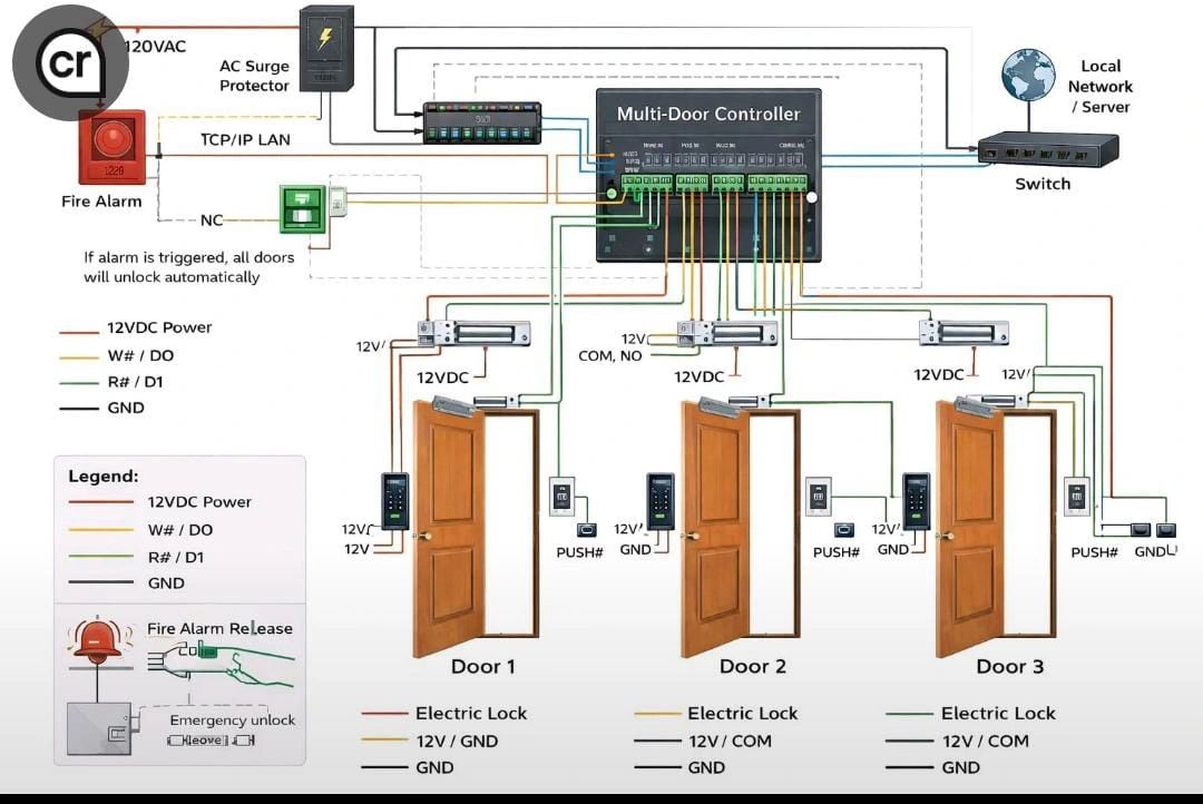
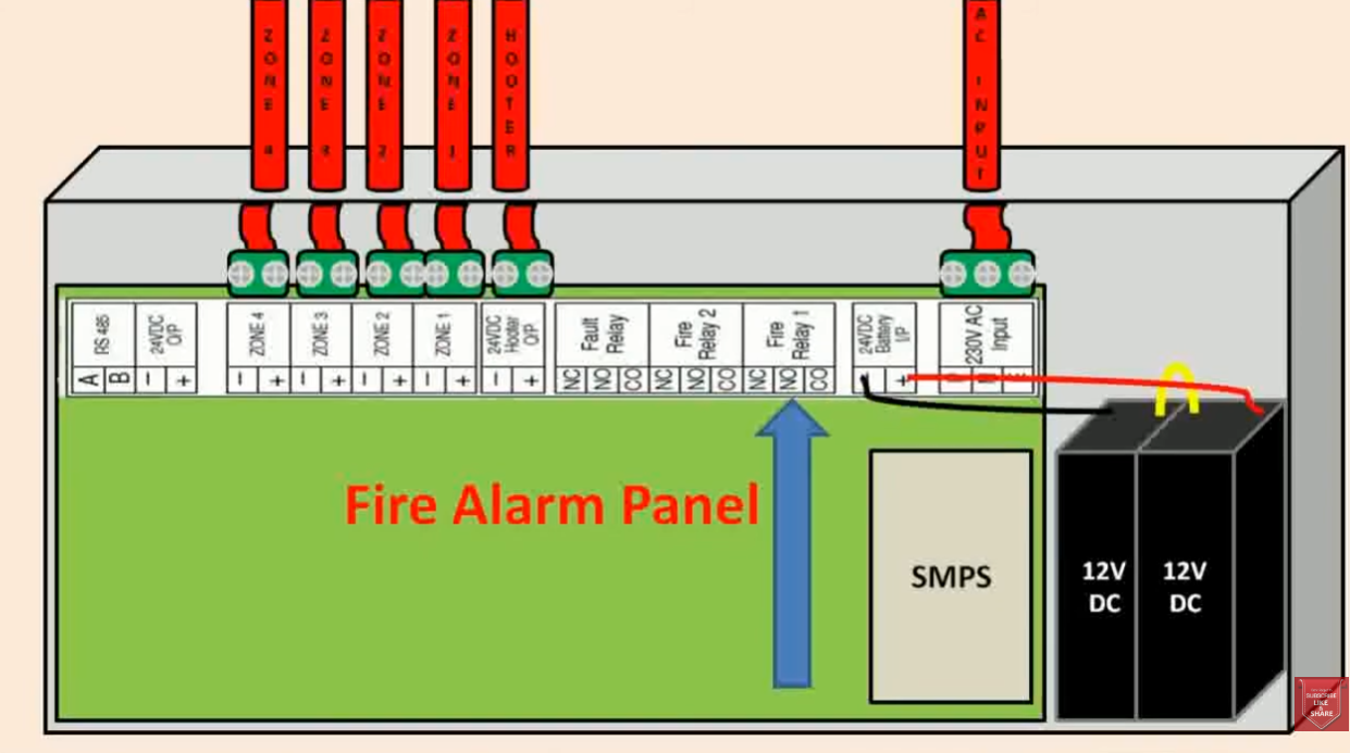
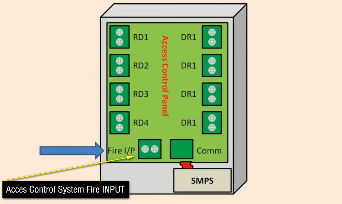
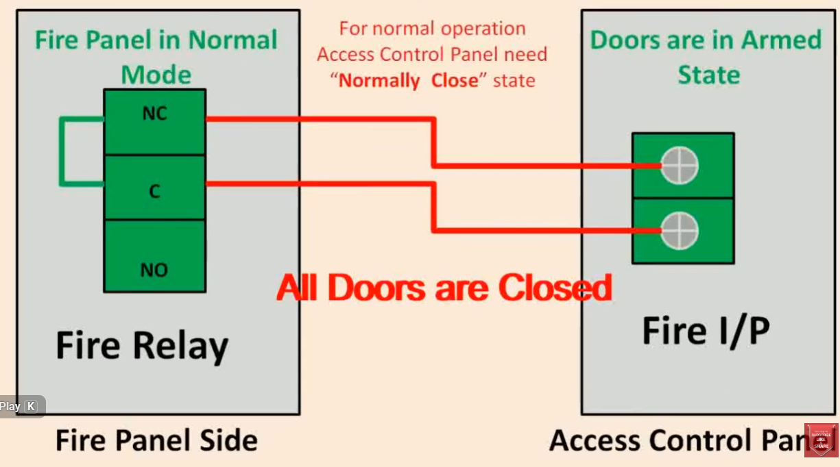
An access control controller contains several important components that work together to manage door access and security operations. Each component has a specific function in controlling devices, processing user data, and operating the locking system.
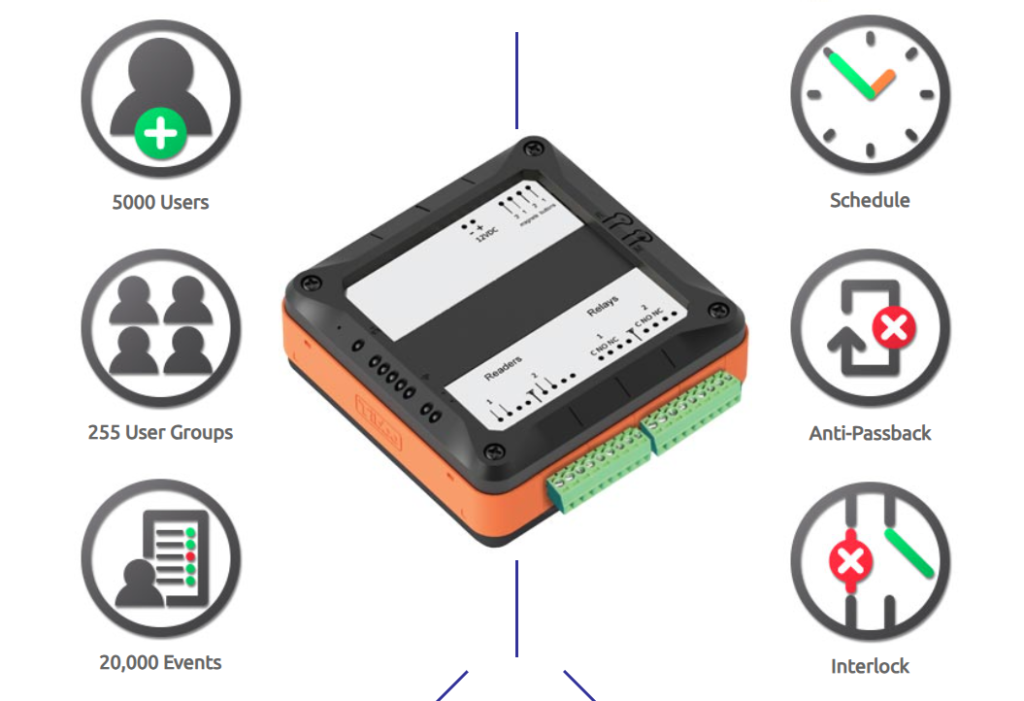
The power input terminal is used to supply electrical power to the controller board. It provides the required voltage for operating the controller and connected devices. Some controllers also support backup battery connections to continue working during power failures.
The processor or CPU is the main processing unit of the controller. It receives data from readers and sensors, processes access requests, checks permissions, and controls outputs such as door locks and alarms. It performs all logical operations inside the access control system.
Memory storage is used to store user information, card numbers, fingerprints, passwords, access schedules, and event logs. The controller uses this memory to verify users and maintain access records.
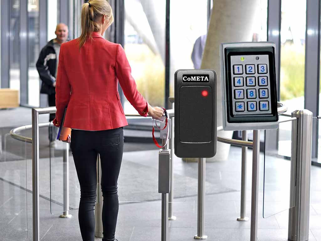
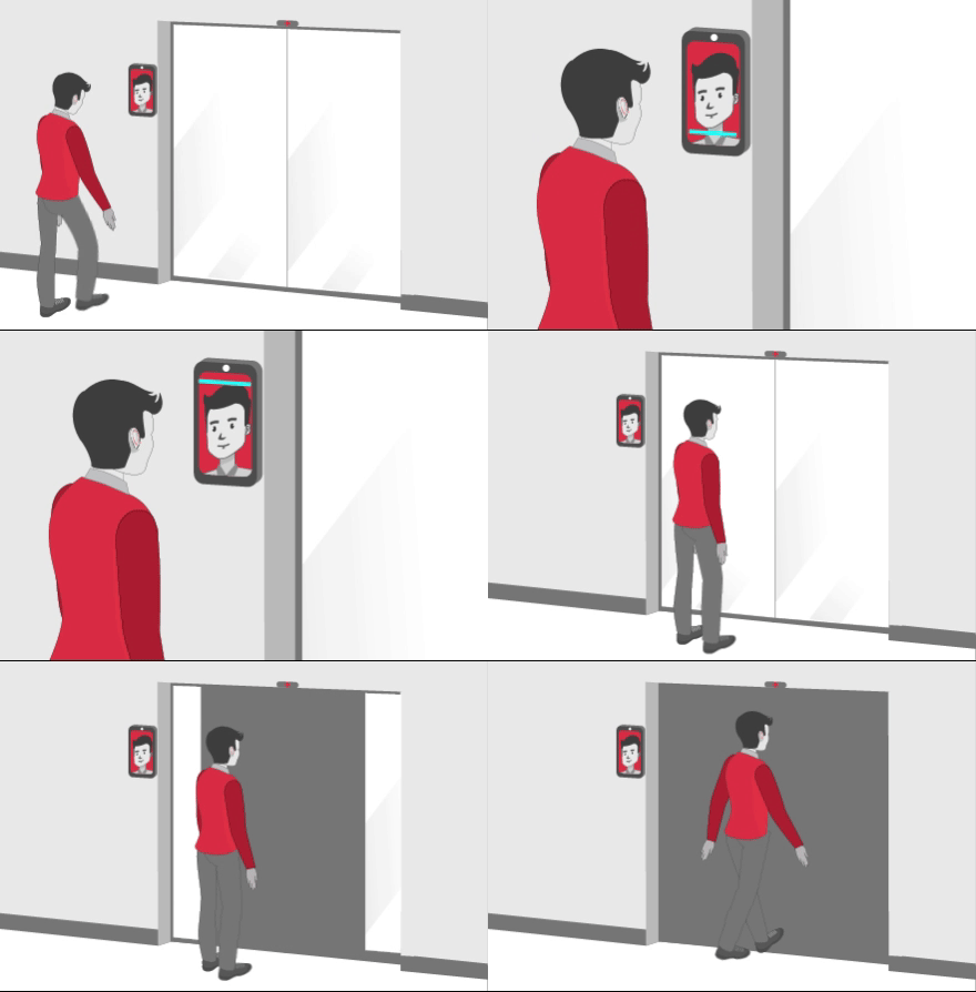
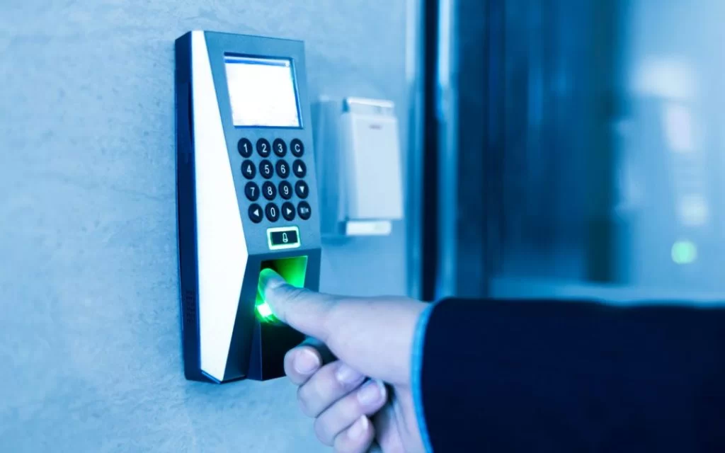
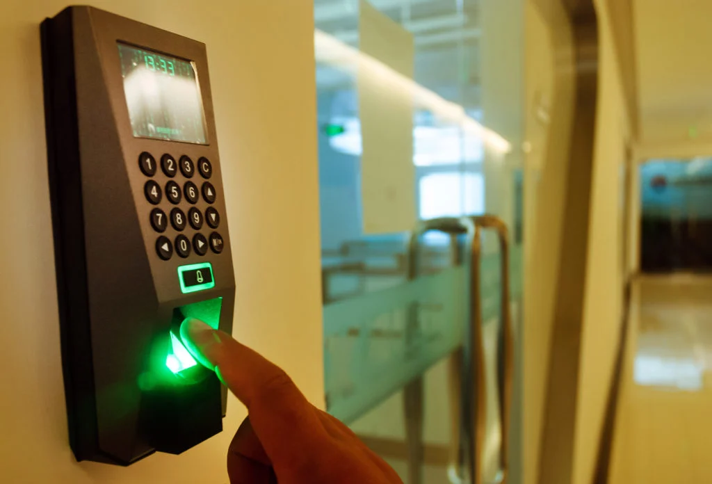
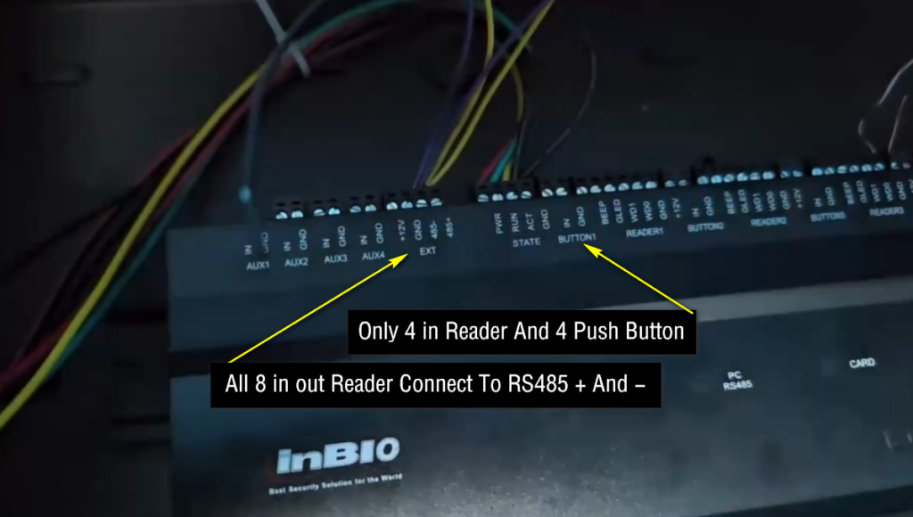
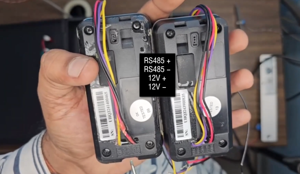
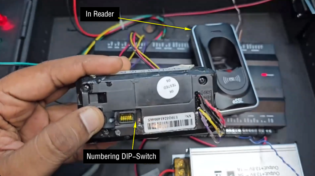
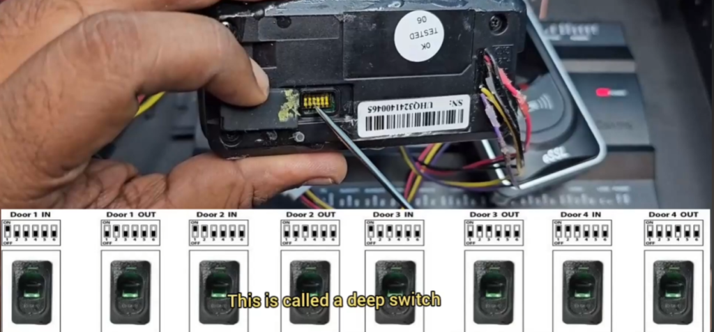
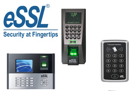
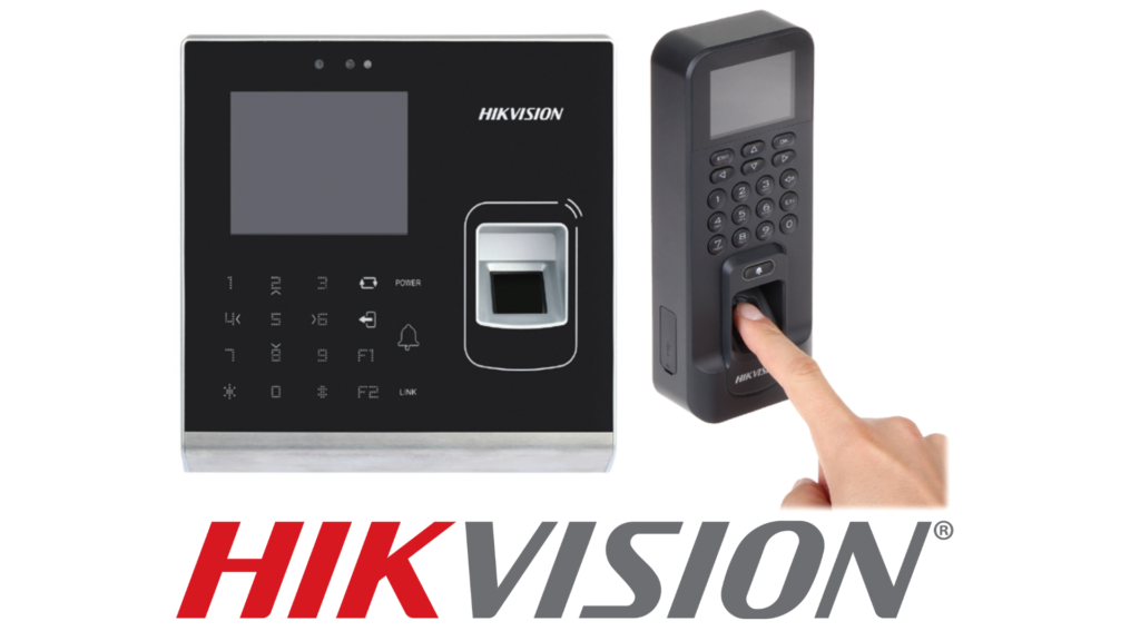
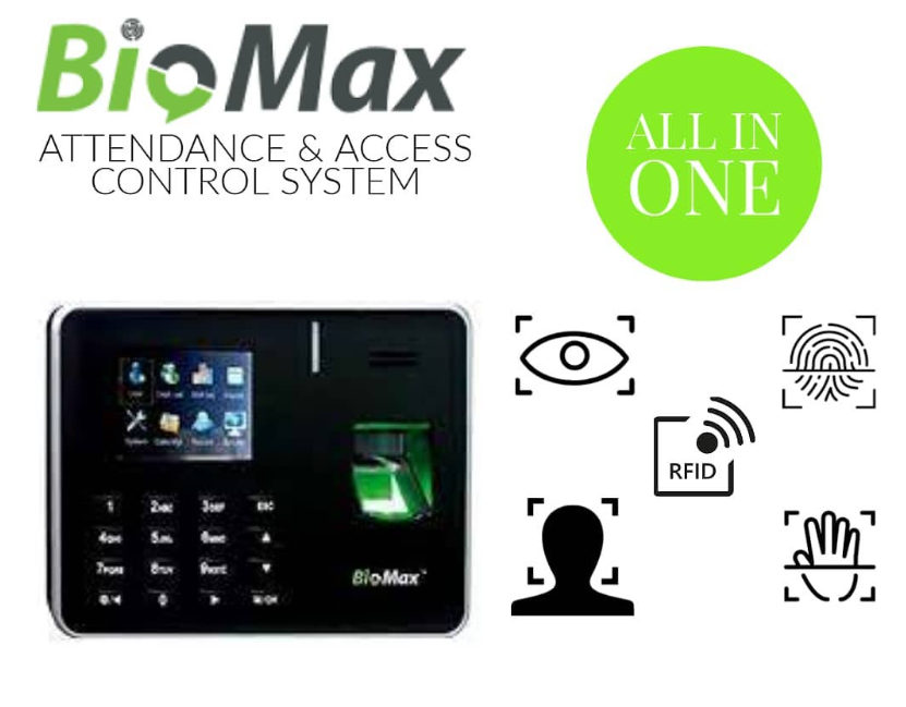
Reader terminals are used for connecting RFID card readers, fingerprint scanners, or keypad devices. These terminals receive data from input devices and transfer it to the controller for verification.
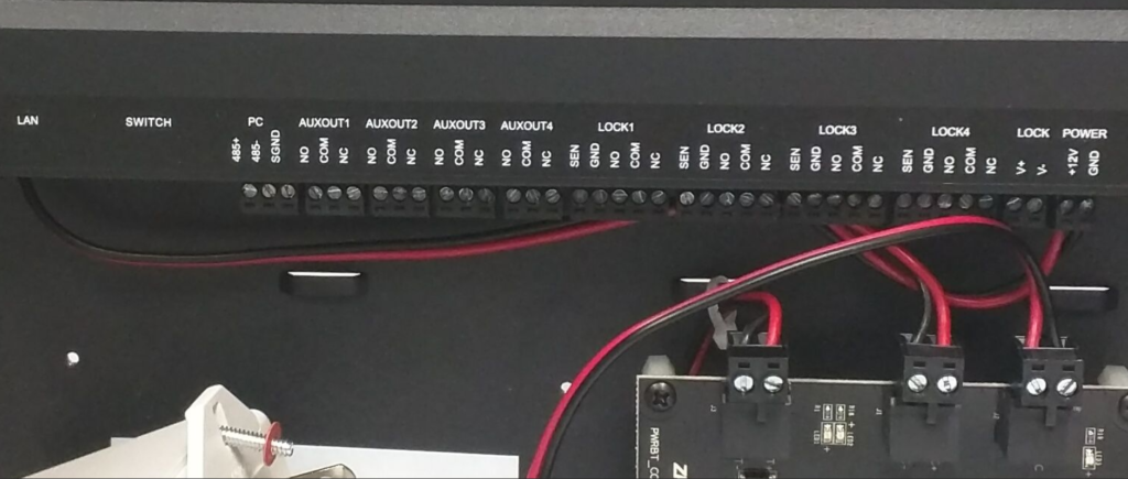
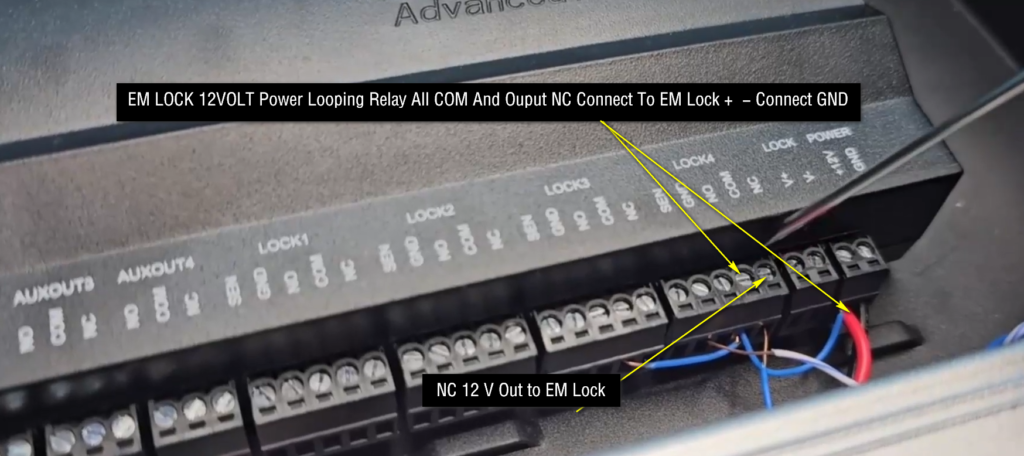
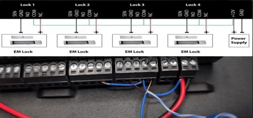

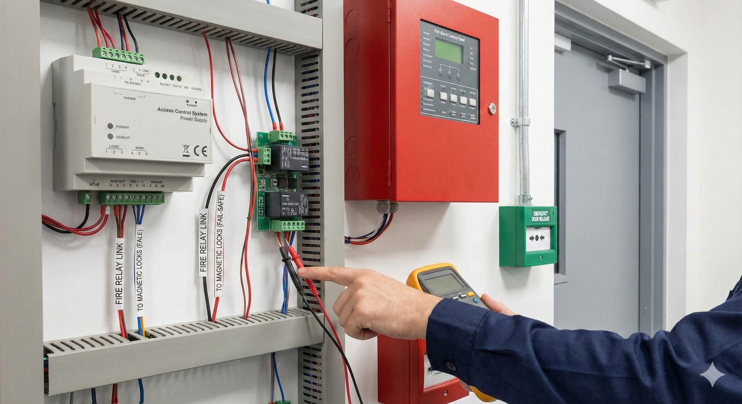
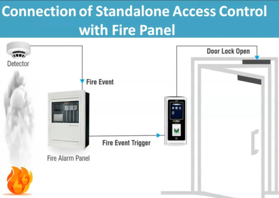
Lock output terminals are responsible for controlling door locks such as EM locks and electric strike locks. These outputs work through relay circuits that switch power to the locking device.
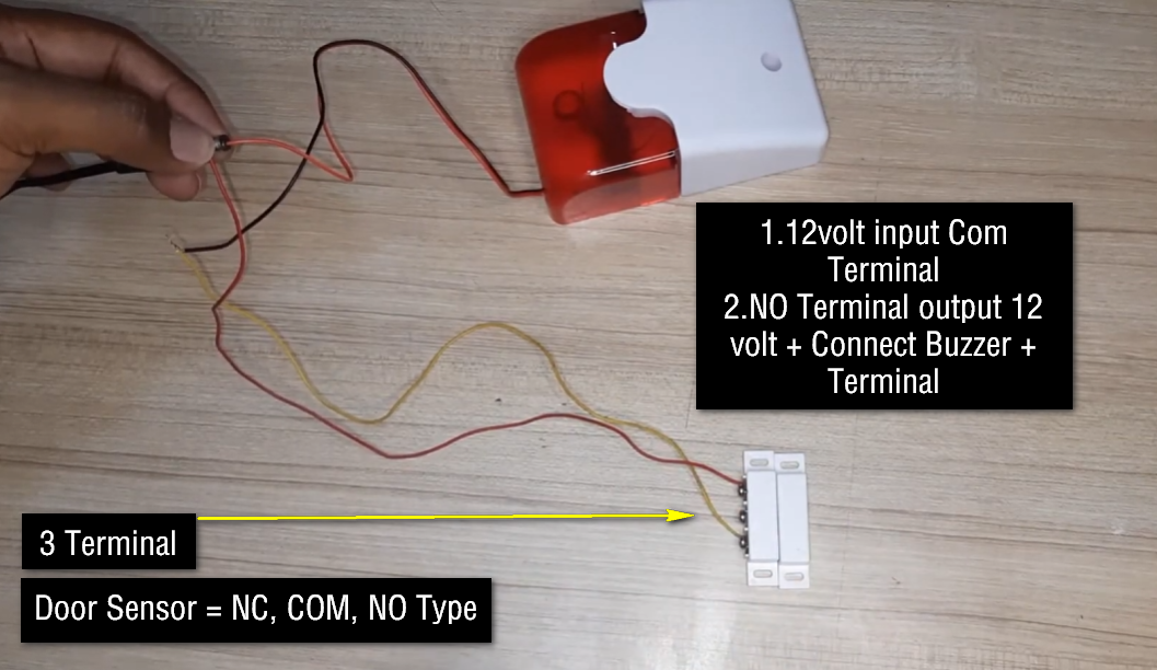
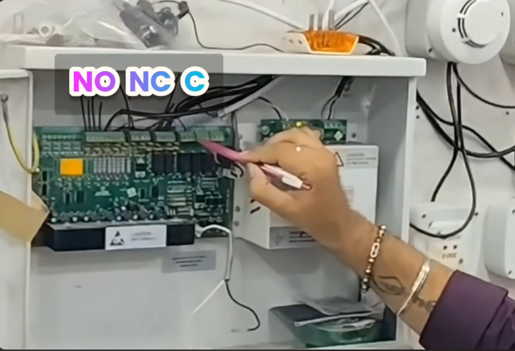
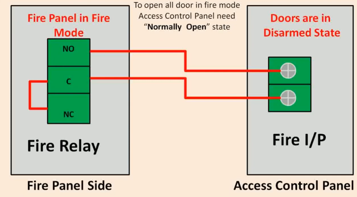
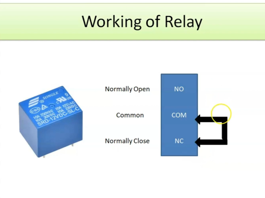
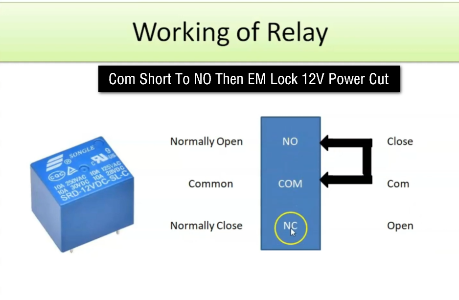
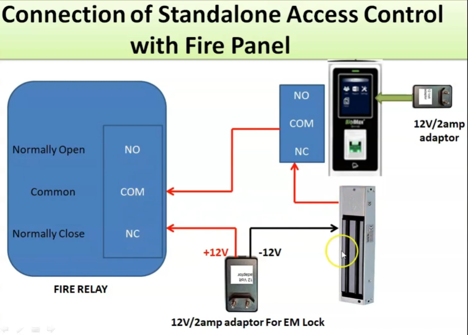
The COM, NO, and NC terminals are relay connection points used for different lock wiring methods. COM stands for Common, NO stands for Normally Open, and NC stands for Normally Closed. These terminals determine how the lock behaves during normal and activated conditions.
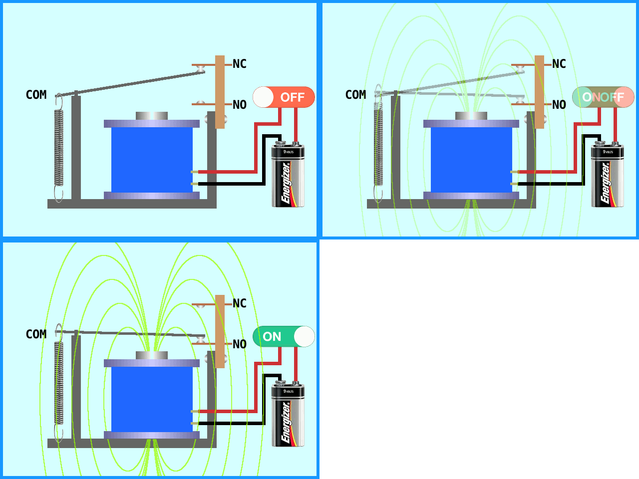
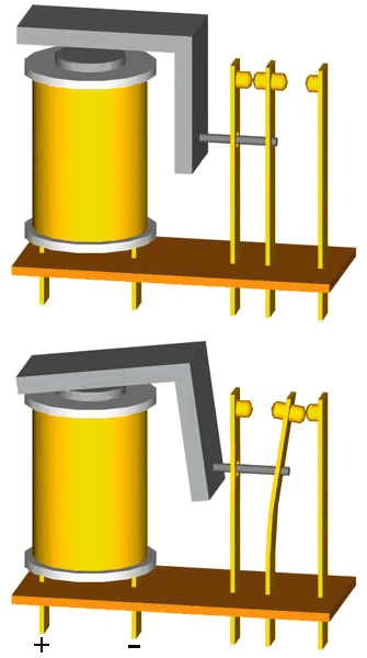
The relay module is an important internal component that acts like an electronic switch. It allows the controller to safely control higher-voltage locking devices by switching power on or off.
Exit button terminals are used for connecting push buttons installed inside the building. When the button is pressed, the controller unlocks the door to allow people to exit.
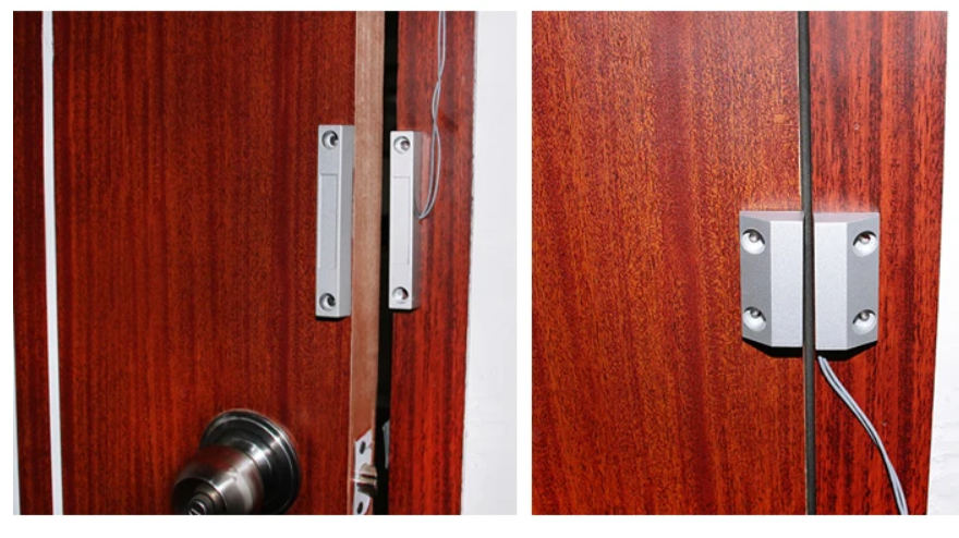
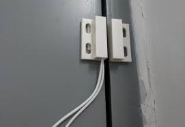
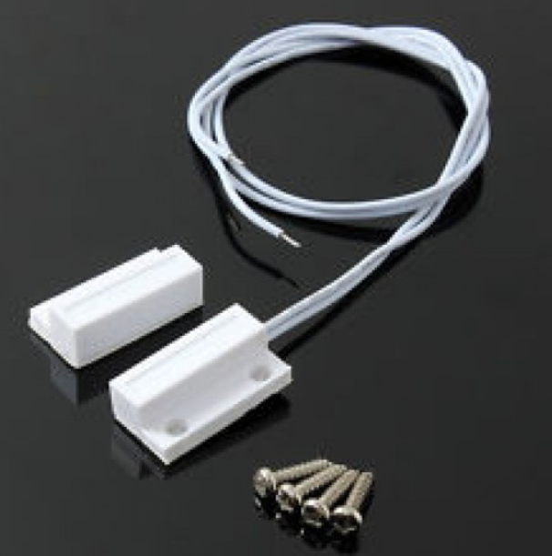
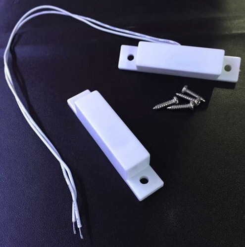
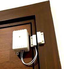
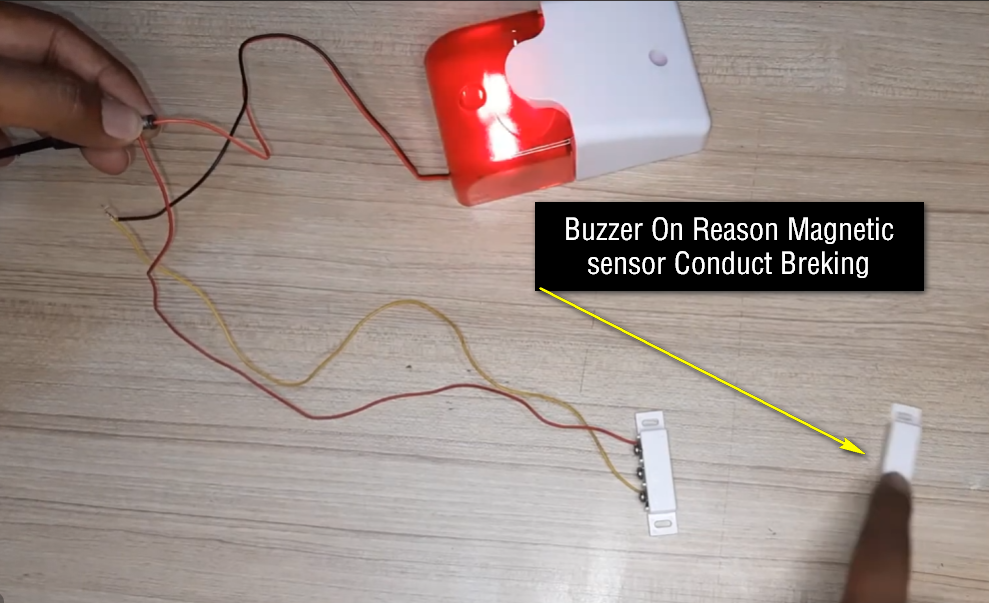
Door sensor terminals connect magnetic door sensors that monitor whether the door is open or closed. These sensors help detect forced entry, door left open conditions, or abnormal activity.
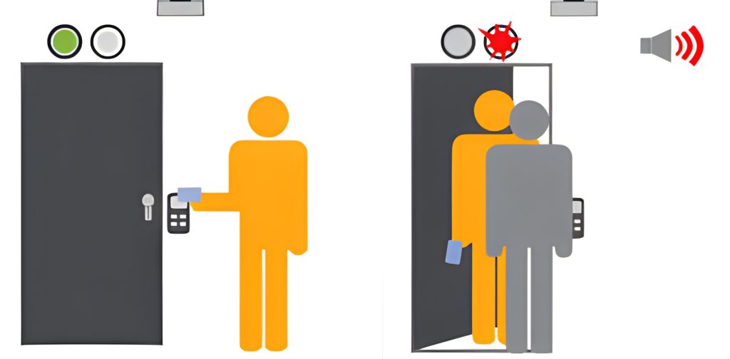
Alarm output terminals are used to connect sirens, buzzers, or alarm systems. The controller can activate alarms during unauthorized access attempts or system faults.
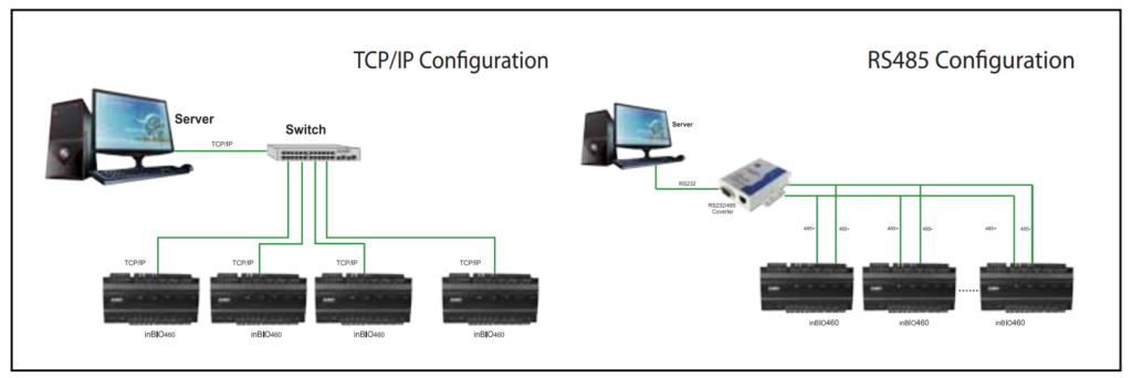
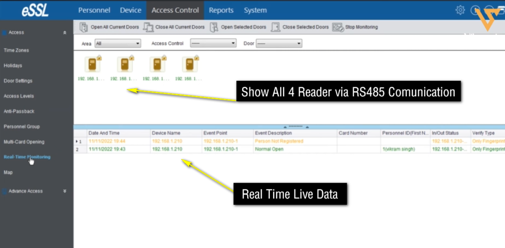
RS485 communication ports allow multiple controllers and devices to communicate over long distances. This communication method is commonly used in large access control systems.
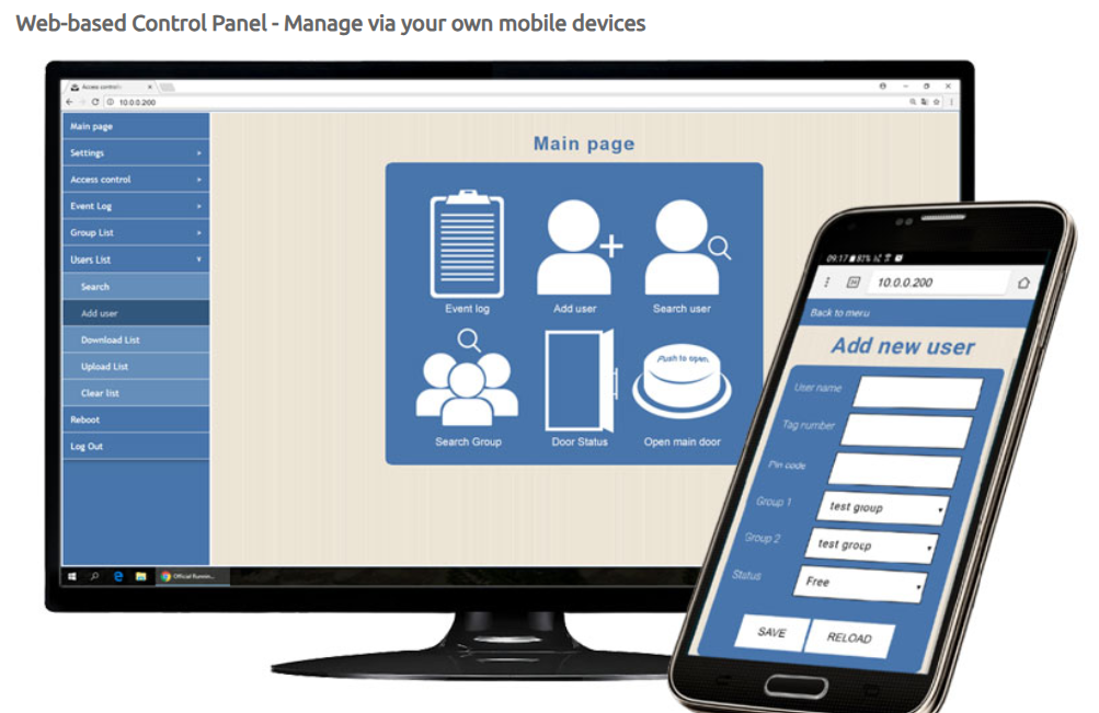
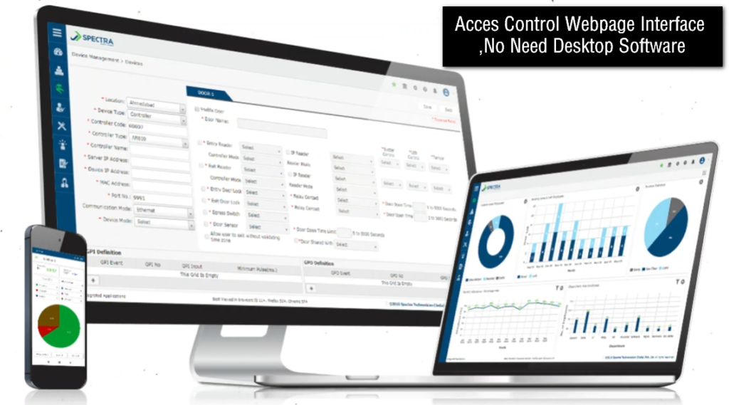
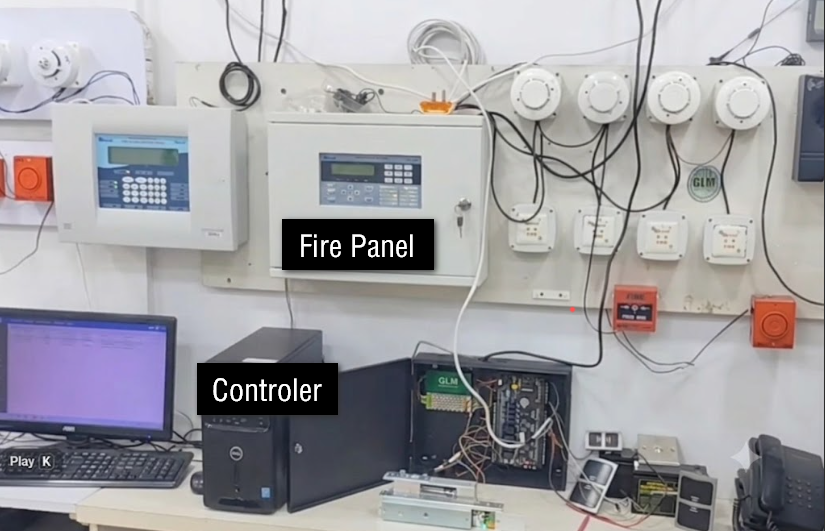
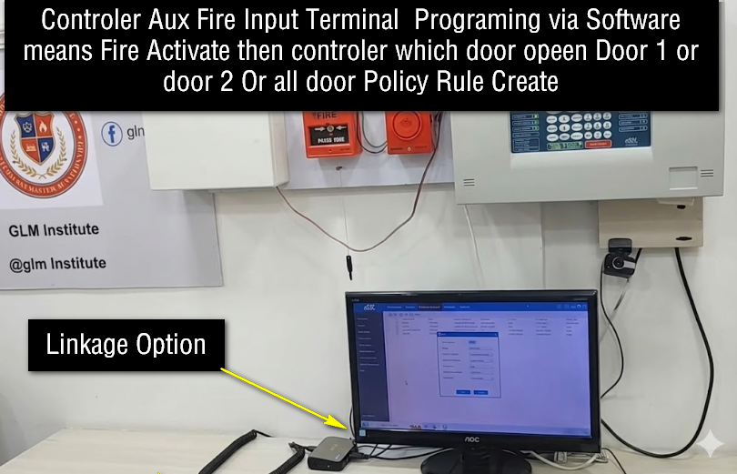
TCP/IP network ports allow the controller to connect to a computer network. Through the network connection, administrators can manage users, monitor events, and control doors using software.
LED status indicators are used to display system conditions such as power status, communication activity, relay operation, and fault conditions. These indicators help technicians during installation and troubleshooting.
Input and output ports are used for connecting additional external devices such as sensors, alarms, intercom systems, or automation equipment.
The firmware or embedded software inside the controller controls all hardware operations and system functions. It manages authentication, communication, event recording, timing operations, and security rules.
All these components work together to make the access control controller the central management device of the entire access control system.
Short Quick Explain:
- Power input terminal supplies power to the controller.
- Processor (CPU) controls all controller operations.
- Memory storage saves user data and access records.
- Reader terminals connect RFID or biometric devices.
- Lock output terminals control door locks.
- COM terminal is the common relay connection point.
- NO terminal remains open in normal condition.
- NC terminal remains closed in normal condition.
- Relay module switches lock power ON or OFF.
- Exit button terminal connects the inside exit switch.
- Door sensor terminal monitors door open or close status.
- Alarm output terminal activates alarms or buzzers.
- RS485 port enables communication between controllers.
- TCP/IP port connects the controller to a network.
- LED indicators show power and system status.
- Input/output ports connect external security devices.
- Backup battery terminal supports power failure operation.
- Firmware controls system logic and access management.