
MPLS L2 LAB
In L2VPNs, the provider act as a transparent L2 switch, providing ports to the customer.
E-Line is essentially a P2P circuit, where the customer does not engage in any routing with the provider. in L3VPNs, customer and provider must agree on a routing protocol, link IP addresses and routing is configured between them.
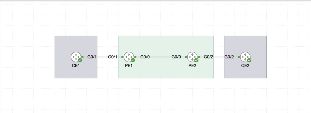
In this example, customer has CE1 and CE2 in 2 remote locations, and wishes to use a L2 circuit from the provider. CE1 and CE2 connect to the ISP Edge routers P1 and PE2, and the provider transports the traffic between the 2 CE nodes, as if the 2 routers were directly connected.
On PE and PE2, we enable:
- IGP, in this case it will be OSPF.
- MPLS LDP.
Let’s start with OSPF.
					PE1 Router Configuration
.........................
int lo0
ip address 1.1.1.1 255.255.255.255
ip ospf 10 area 0 !
int gi0/0
ip address 172.16.1.1 255.255.255.0
ip ospf 10 area 0 !
router-id 1.1.1.1
					PE2 Router Configuration
.........................
int lo0
ip address 2.2.2.2 255.255.255.255
ip ospf 10 area 0
int gi0/0
ip address 172.16.1.2 255.255.255.0
ip ospf 10 area 0
router-id 2.2.2.2
At this point, we have OSPF adjacency enabled between PE1 and PE2 and Loopback addresses advertised.
Let’s enable MPLS LDP. We have 2 options, either we enable LDP per interface, or globally under OSPF process.
					PE1(config)#router ospf 10
PE1(config-router)#mpls ldp autoconfig

and on PE2

PE2(config)#router ospf 10
PE2(config-router)#mpls ldp autoconfig
In this next section, we validate our configuration so far.
					PE1#sh ip ospf neighbor

Neighbor ID     Pri   State           Dead Time   Address         Interface
2.2.2.2           1   FULL/BDR        00:00:30    172.16.1.2      GigabitEthernet0/0
PE1#sh ip route ospf | b Gateway
Gateway of last resort is not set

      2.0.0.0/32 is subnetted, 1 subnets
O        2.2.2.2 [110/2] via 172.16.1.2, 01:36:55, GigabitEthernet0/0
PE1#sh mpls ldp neighbor
    Peer LDP Ident: 2.2.2.2:0; Local LDP Ident 1.1.1.1:0
        TCP connection: 2.2.2.2.53184 - 1.1.1.1.646
        State: Oper; Msgs sent/rcvd: 114/115; Downstream
        Up time: 01:32:32
        LDP discovery sources:
          GigabitEthernet0/0, Src IP addr: 172.16.1.2
        Addresses bound to peer LDP Ident:
          172.16.1.2      2.2.2.2
The next step is to configure the interfaces facing customer CE nodes for the P2P E-Line service. Customer will be totally oblivious to how the traffic is transported between CE and CE2, as it does not interact with the provider’s routing.
On both PE1 and PE2 we configure the following:
					PE1(config)#pseudowire-class LAB1
PE1(config-pw-class)#encapsulation mpls
PE1(config-pw-class)#ex
!
PE1(config)#int gigabitEthernet 0/1
PE1(config-if)#xconnect 2.2.2.2 12 pw-class LAB1

PE2(config)#pseudowire-class LAB1
PE2(config-pw-class)#encapsulation mpls
PE2(config-pw-class)#ex
!
PE2(config)#int gigabitEthernet 0/1
PE2(config-if)#xconnect 1.1.1.1 12 pw-class LAB1
The xconnect configuration must reach to the remote PE loopback address and VC ID (12 in our case is a trivial number) must match for the xconnect.
Once the Xconnect is configured on both interfaces, you would notice a log message indicating an LDP session is up. This is a targeted LDP session between PE1 and PE2.
*Apr 27 21:36:34.896: %LDP-5-NBRCHG: LDP Neighbor 1.1.1.1:0 (1) is UP
Let’s validate the status of the xconnect:
					PE1#sh xconnect all
Legend:    XC ST=Xconnect State  S1=Segment1 State  S2=Segment2 State
  UP=Up       DN=Down            AD=Admin Down      IA=Inactive
  SB=Standby  HS=Hot Standby     RV=Recovering      NH=No Hardware

XC ST  Segment 1                         S1 Segment 2                         S2
------+---------------------------------+--+---------------------------------+--
UP pri   ac Gi0/1:3(Ethernet)            UP mpls 2.2.2.2:12                   UP
PE1#sh xconnect all detail
Legend:    XC ST=Xconnect State  S1=Segment1 State  S2=Segment2 State
  UP=Up       DN=Down            AD=Admin Down      IA=Inactive
  SB=Standby  HS=Hot Standby     RV=Recovering      NH=No Hardware

XC ST  Segment 1                         S1 Segment 2                         S2
------+---------------------------------+--+---------------------------------+--
UP pri   ac Gi0/1:3(Ethernet)            UP mpls 2.2.2.2:12                   UP
            Interworking: none                   Local VC label 17
                                                 Remote VC label 17
                                                 pw-class: LAB1
As a final validation, let’s test if we can ping CE2 from CE1.
					CE1#ping 10.10.1.2
Type escape sequence to abort.
Sending 5, 100-byte ICMP Echos to 10.10.1.2, timeout is 2 seconds:
!!!!!
Success rate is 100 percent (5/5), round-trip min/avg/max = 7/15/26 ms
Basic MPLS Check Commands
.........................
1.Check MPLS Interfaces
show mpls interfaces
interface GigabitEthernet0/0
mpls ip

Shows which interfaces have MPLS enabled
Must be enabled for L2 MPLS to work


2.Check LDP Neighbors
show mpls ldp neighbor

Displays MPLS neighbors
If no neighbor → MPLS will not work


3.Check MPLS Forwarding Table
show mpls forwarding-table


Shows label bindings and forwarding paths
Important to verify label switching


L2 MPLS (Pseudowire / xconnect) Commands
........................................
4.Check Pseudowire Status
show mpls l2transport vc

Shows Virtual Circuit (VC) status
Output shows:
VC ID
Peer IP
Status (UP/DOWN)


5.Check Xconnect (Layer 2 VPN)
show xconnect all

Shows all Layer 2 connections (Ethernet, VLAN, etc.)


6.Check Detailed VC Info
show mpls l2transport vc detail


Provides deep info:
Encapsulation type
Labels
MTU
Packet statistics


LDP & Label Debugging
.....................
7.Check LDP Bindings
show mpls ldp bindings

Shows label mapping between routers


8.Check MPLS Ping (Very Important)
ping mpls pseudowire <peer-ip> vc-id <id>

Tests L2 MPLS connectivity
Helps identify VC issues


Common Troubleshooting Commands
...............................
show ip route
show ip cef
show ip interface brief

Check interface → show ip int brief
Check MPLS enabled → show mpls interfaces
Check LDP neighbor → show mpls ldp neighbor
Check VC → show mpls l2transport vc
Check xconnect → show xconnect all
E-LAN is similar to E-Line in terms of concept and how the customer does not interact and route with the provider. However, E-LAN is not P2P, but more as a full mesh.
Here, the provider act as a switch, enabling the end CEs to learn each other MAC addresses and therefore communicate.
I expanded on the previous example by adding PE3 and CE3 to existing nodes. The goal is to have all 3 CEs communicating
As we have done previously for PE1 and PE2, I have also added OSPF to PE3, routing loopback0 (3.3.3.3) and enabled MPLS LDP.
The steps to configure E-LAN or VPLS are as follows:
- Configure service instance ethernet under the interface facing CE.
- Configure a bridge domain, this will be the virtual switch where MAC addresses will be learnt.
- Configure the VFI (Virtual Forwarding Instance), where VPN ID must be unique across the domain.
PE2(config)#int gigabitEthernet 2
PE2(config-if)#service instance
PE2(config-if-srv)#encapsulation default
PE2(config-if-srv)#bridge-domain 200
PE2(config-if-srv)#exit
!
PE2(config)#bridge-domain 200
Then we configure the VFI
					PE2(config)#l2 vfi LAB2 manual
PE2(config-vfi)#vpn id 1
PE2(config-vfi)#bridge-domain 200
PE2(config-vfi)#
PE2(config-vfi)#neighbor 1.1.1.1 encapsulation mpls
PE2(config-vfi)#neighbor 3.3.3.3 encapsulation mpls
For the validation process, we could run these 2 show commands then finish off with a ping from CE1 to CE2 & CE3.
					PE2#sh bridge-domain
Bridge-domain 200 (3 ports in all)
State: UP                    Mac learning: Enabled
Aging-Timer: 300 second(s)
Maximum address limit: 65536
    GigabitEthernet2 service instance 123
    vfi LAB2 neighbor 1.1.1.1 1
    vfi LAB2 neighbor 3.3.3.3 1
   AED MAC address    Policy  Tag       Age  Pseudoport
					PE2#sh vfi
Legend: RT=Route-target, S=Split-horizon, Y=Yes, N=No

VFI name: LAB2, state: up, type: multipoint, signaling: LDP
  VPN ID: 1
  Bridge-Domain 200 attachment circuits:
  Neighbors connected via pseudowires:
  Peer Address     VC ID        S
  3.3.3.3          1            Y
  1.1.1.1          1            Y
					PING to CE2
CE1#ping 10.10.1.2
Type escape sequence to abort.
Sending 5, 100-byte ICMP Echos to 10.10.1.2, timeout is 2 seconds:
!!!!!
Success rate is 100 percent (5/5), round-trip min/avg/max = 6/9/16 ms
CE1#
PING to CE3
CE1#ping 10.10.1.3
Type escape sequence to abort.
Sending 5, 100-byte ICMP Echos to 10.10.1.3, timeout is 2 seconds:
!!!!!
Success rate is 100 percent (5/5), round-trip min/avg/max = 6/16/29 ms