
Broadcast Domains
What is a broadcast domain
In Ethernet LANs, a broadcast is one-to-all communication, which means that if a node sends a broadcast frame, everybody receives a copy of it. At the Ethernet layer, broadcast frames have a destination MAC address of FF-FF-FF-FF-FF-FF. When a switch receives a frame with this MAC, it sends a copy of the frame out all its interfaces, except the one it received the broadcast on. An example of this behavior is shown in Figure 1.
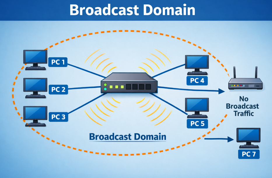
A broadcast domain is a segment of the network where all devices receive a copy of every broadcast frame sent. To better understand the concept let’s look at the example in Figure 1. PC1 sends a broadcast frame with a destination MAC address ff-ff-ff-ff-ff-ff. When the switch receives the frame, it looks in the Ethernet header of the frame and understands, based on the destination MAC, that this is a broadcast frame. The switch then floods the frame out all its ports, except the one it received the frame on (the port towards PC1). In the end, the broadcast frame reached all devices in the LAN – PC1 originated the frame, and PC2,3 and 4 get a copy of it through the switch. Therefore PC1,2,3 and 4 are in one broadcast domain.
Multiswitch broadcast domain
The same network logic applies when the LAN is made of more than one switch. When a node sends a broadcast frame, it is “flooded” to everybody in the broadcast domain.
Let’s look at the example in Figure 2. PC2 sends a broadcast frame with destination MAC address FF-FF-FF-FF-FF-FF. When Switch1 gets the frame, it looks at the Ethernet header and sees based on the MAC address that this is a broadcast, so it floods it out all its port, except the port, it was received on. So the frame goes out the link towards Switch2. When Switch2 receives the frame, it does the same thing as switch1. It understands based on the MAC addresses that this is a broadcast frame and floods it out all its ports. Eventually, the frame goes to every connected device in the LAN. Therefore all devices are in one broadcast domain.
This logic applies to LANs with many switches. If we connect another switch to the topology in Figure 2, the broadcast domain will be extended across the new switch, and so on.
Broadcast Domains and Routers
At this point, you may be wondering when this flood of broadcast ends and whether a whole network environment a one broadcast domain. If we want to break down a broadcast domain into smaller domains, we use a router. Routers don’t flood broadcast frames but instead decapsulate the ethernet frames and act upon the layer 3 information within the IP packets.
Let’s look at the example in Figure 2. PC2 sends a broadcast frame. The switch floods the frame out all its ports, so PC1,3 and router 1 get a copy of it. But note that the router doesn’t flood the frame to PC4 and PC5, because routers don’t forward broadcast frames and the domain ends there. Every interface of the router creates a separate broadcast domain as shown in Figure 3.
There is another way to split a broadcast domain into multiple ones. It can be done with a technology called Virtual LANs (VLANs). We will have a closer look at VLANs in a separate section in this course, but for now, just have it in mind.
Summary
So in summary, the most important points about broadcast domains are:
- A broadcast domain is a segment of the network where all devices receive a copy of every broadcast frame sent.
- Switches flood broadcast traffic out all interfaces, except the one they received the broadcast on.
- Routers stop broadcast flood and break broadcast domains.
- A broadcast domain can be split into smaller one with VLANs
Broadcast Domain
A broadcast domain is a logical part of a network where a broadcast message sent by one device is received by all other devices within that same network segment. Broadcast messages are used when a device wants to communicate with all devices, for example when using ARP to find the MAC address of another device.
How Broadcast Domain Works
When a device sends a broadcast frame (destination MAC = FF:FF:FF:FF:FF:FF), every device in that broadcast domain receives and processes it. This can increase network traffic if the network is large.
Example
Imagine a network with 5 computers connected to a switch:
- PC1 sends a broadcast message (e.g., ARP request: “Who has this IP?”)
- The switch forwards this broadcast to all ports
- PC2, PC3, PC4, and PC5 all receive it
👉 So, all 5 devices are part of one broadcast domain
Role of Network Devices
1. Hub
- All devices in one broadcast domain
- Broadcast goes to every device
2. Switch
- By default, one broadcast domain
- Broadcast is forwarded to all ports
3. Router
- Breaks broadcast domains
- Each interface of a router = separate broadcast domain
Another Example (With Router)
- 2 switches connected to a router
- Each switch has 5 PCs
👉 Result:
- Switch 1 → 1 broadcast domain
- Switch 2 → 1 broadcast domain
- Router separates them → total 2 broadcast domains
Broadcast from Switch 1 will NOT reach Switch 2.
Key Points
- Broadcast domain = area where broadcast traffic spreads
- Switch does NOT break broadcast domain (by default)
- Router breaks broadcast domain
- Large broadcast domains can reduce network performance
Real-Life Analogy
Think of a broadcast domain like a classroom announcement:
If a teacher speaks, all students in that classroom hear it. But students in another classroom (separated by walls = router) cannot hear it.
Conclusion
A broadcast domain defines how far broadcast traffic can travel in a network. Controlling broadcast domains (using routers or VLANs) helps improve network performance and security.
Difference Chart: Collision Domain vs Broadcast Domain
| Feature | Collision Domain | Broadcast Domain |
|---|---|---|
| Definition | Network area where data collisions can occur | Network area where broadcast messages are received |
| Main Issue | Collision of data packets | Flooding of broadcast traffic |
| Cause | Multiple devices sending data at same time | One device sending to all devices |
| Affected Devices | Only devices in same collision area | All devices in that broadcast domain |
| Works With | Half-duplex Ethernet (hub-based) | All Ethernet networks |
| Hub | One collision domain | One broadcast domain |
| Switch | Each port = separate collision domain | Entire switch = one broadcast domain |
| Router | Each interface = separate collision domain | Each interface = separate broadcast domain |
| Breaks Domain | Switch / Bridge | Router / VLAN |
| Performance Impact | High collisions = slow network | Too many broadcasts = congestion |
| Example | 4 PCs in hub → 1 collision domain | 10 PCs in switch → 1 broadcast domain |
Simple One-Line Difference
- Collision Domain → Deals with data collision problem
- Broadcast Domain → Deals with broadcast traffic spreading
Quick Example
- Hub network → 1 Collision + 1 Broadcast Domain
- Switch network → Multiple Collision + 1 Broadcast Domain
- Router network → Multiple Collision + Multiple Broadcast Domain
Easy Analogy
- Collision Domain = People talking at same time → clash ❌
- Broadcast Domain = One person announcing → everyone hears ✅