
Collision Domain
To understand what a collision domain is, we have to look a little bit in the past when Ethernet LANs were built using devices like Hubs and Bridges.
Ethernet LAN with Hubs
Ethernet Hub is a network device that is used for connecting multiple nodes and making them act as connected to a single network segment. It works purely at the physical layer of the OSI model. It has multiple ports, in which the incoming electrical signals on one port are repeated at the output of every other port. There is no forwarding logic at all.
A Hub makes all connected devices to be part of one single network segment because every electrical signal on every cable is replicated to all other cables. This creates a single shared medium and a network collision occurs when more than one device attempts to send a frame on the segment at the same time.
Figure 1 shows an example of two PCs trying to send an Ethernet frame simultaneously. Because they are connected to a shared network segment, they are part of one collision domain. It is also visible in Figure 2 that only one the PCs in the collision domain may transmit at any one time otherwise collision occurs.
Carrier-sense multiple access with Collision Detection (CSMA/CD)
So at that point, you may be wondering if collisions happen all the time, how are devices connected to an Ethernet Hub even able to communicate? There is a media access control method called CSMA/CD that devices use when trying to communicate over a shared medium. CSMA/CD stands for Carrier Sense Multiple Access with Collision Detection. The key here is the Collision Detection. When a device wants to transmit a frame, it checks to see if the segment is free. If the segment is not free, the device waits a random amount of time before retransmitting. If the network segment is free and two devices send frames at the same time, their signals collide. When the collision is detected, they both stop and wait a random amount of time before retransmitting.
To understand what is behind Carrier Sense Multiple Access with Collision Avoidance, let’s look at each component individually:
- Carrier sense (CA): The idea that nodes may only send data over the network if the shared medium is free.
- Multiple access (MA): Several nodes share a network segmen,t so they need an access method to resolve collisions.
- Collision detection (CD): If a collision does occur, it will be detected and the transmission will be tried again after a random amount of time.
The concept of collision domains also applies in wireless networks because the radio signals traverse a shared medium, which is the wi-fi radio spectrum. So all things we have said by now apply to Wireless networks as well – only one node in a wireless LAN may transmit at any one time, otherwise collision occurs as shown in Figure 3.
Several techniques were introduced over the years to resolve this scaling problem. For now, we are going to focus only on the Wired LANs.
Ethernet Bridges
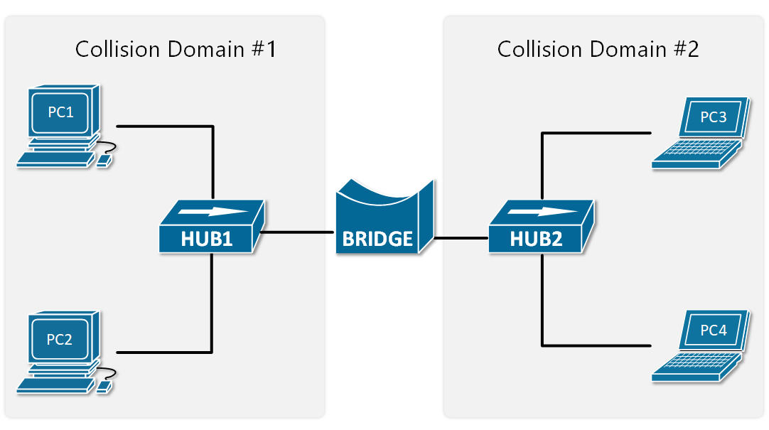
Ethernet Bridges are the predecessor of modern LAN switches. They were introduced to resolve the scaling problem with shared segments and collisions. Bridges are layer 2 devices, which means they can read the Ethernet Header of the frames they forward and make decisions based on the information in the headers. This eliminated the need to send all frames out all ports, which practically means to repeat all electrical signals out to all ports. Therefore, Ethernet bridges split a network segment into two collision domains as shown in Figure 4.
At the time, that was a huge scaling improvement and enabled the creation of larger LAN segments. As local area networks grew bigger, demand for more scale was needed so devices with better performance and more interfaces were introduced – LAN switches.
Ethernet Switches
LAN switches completely resolve the problem with collisions. They operate at layer 2 of the OSI model, meaning that they look at the ethernet header and trailer. Their main advantage is that all their ports can operate in full-duplex, meaning they can simultaneously transmit and receive frames on any given port at any given time. Because of this, the media access algorithm for collision detection (CSMA/CD) is no longer required and is disabled by default. Another big advantage of switches is that they forward frames based on MAC addresses, so any given frame doesn’t need to be sent to all ports as hubs do.
That’s why these days all wired local area networks are built with LAN switches.
Troubleshooting Collisions
Cisco switches have pretty sophisticated interface statistics that are sufficient for troubleshooting problems in Ethernet collision domains. There are a few counters we have to check out.
Deferred frames
The deferred counter increases when the switch tries to send a frame out an interface but finds the carrier busy (Carrier Sense). This does not mean that there is a problem and is part of the normal Ethernet switching and forwarding process. Note the following example:
					SW1#show interface Fa0/1
FastEthernet0/1 is up, line protocol is up (connected)
  Hardware is Lance, address is 0040.0ba6.3601 (bia 0040.0ba6.3601)
 Description: LINK-TO-SW2
 BW 100000 Kbit, DLY 1000 usec,
     reliability 255/255, txload 1/255, rxload 1/255
  Encapsulation ARPA, loopback not set
  Keepalive set (10 sec)
  Full-duplex, 100Mb/s
  input flow-control is off, output flow-control is off
  ARP type: ARPA, ARP Timeout 04:00:00
  Last input 00:00:08, output 00:00:05, output hang never
  Last clearing of "show interface" counters never
  Input queue: 0/75/0/0 (size/max/drops/flushes); Total output drops: 0
  Queueing strategy: fifo
  Output queue :0/40 (size/max)
  5 minute input rate 5343 bits/sec, 231 packets/sec
  5 minute output rate 32131 bits/sec, 176 packets/sec
     94356 packets input, 19334351 bytes, 0 no buffer
     Received 956 broadcasts, 0 runts, 0 giants, 0 throttles
     4 input errors, 43 CRC, 0 frame, 0 overrun, 0 ignored, 0 abort
     0 watchdog, 0 multicast, 0 pause input
     0 input packets with dribble condition detected
     237657 packets output, 26123570 bytes, 0 underruns
     0 output errors, 54 collisions, 10 interface resets
     0 babbles, 75 late collision, 1213 deferred
     0 lost carrier, 0 no carrier
     0 output buffer failures, 0 output buffers swapped out
Collisions
It counts the number of collisions that occurred after the frame was sent by the switch. Check the following example:
					SW1#show interface Fa0/2
FastEthernet0/1 is up, line protocol is up (connected)
  Hardware is Lance, address is 0040.0ba6.3601 (bia 0040.0ba6.3601)
  Description: LINK-TO-SW3
 BW 100000 Kbit, DLY 1000 usec,
     reliability 255/255, txload 1/255, rxload 1/255
  Encapsulation ARPA, loopback not set
  Keepalive set (10 sec)
  Full-duplex, 100Mb/s
  input flow-control is off, output flow-control is off
  ARP type: ARPA, ARP Timeout 04:00:00
  Last input 00:00:08, output 00:00:05, output hang never
  Last clearing of "show interface" counters never
  Input queue: 0/75/0/0 (size/max/drops/flushes); Total output drops: 0
  Queueing strategy: fifo
  Output queue :0/40 (size/max)
  5 minute input rate 3261 bits/sec, 321 packets/sec
  5 minute output rate 54873 bits/sec, 2420 packets/sec
     954356 packets input, 192433351 bytes, 0 no buffer
     Received 956 broadcasts, 0 runts, 0 giants, 0 throttles
     0 input errors, 0 CRC, 0 frame, 0 overrun, 0 ignored, 0 abort
     0 watchdog, 0 multicast, 0 pause input
     0 input packets with dribble condition detected
     542357 packets output, 74263570 bytes, 0 underruns
     0 output errors, 432 collisions, 10 interface resets
     0 babbles, 0 late collision, 320 deferred
     0 lost carrier, 0 no carrier
     0 output buffer failures, 0 output buffers swapped out
As explained above, it is normal to have some collisions in the network, but if the number is high, it might indicate that the collision domain is too big and must be broken down into smaller ones.
Late Collisions
If a collision is detected after the first 512 bits of the frame was sent, it is counted as a late collision. It usually points to a duplex mismatch, incorrect cabling or that the collision domain is too big.
					SW1#show interface Fa0/3
FastEthernet0/1 is up, line protocol is up (connected)
  Hardware is Lance, address is 0040.0ba6.3601 (bia 0040.0ba6.3601)
  Description: LINK-TO-SW4
 BW 100000 Kbit, DLY 1000 usec,
     reliability 255/255, txload 1/255, rxload 1/255
  Encapsulation ARPA, loopback not set
  Keepalive set (10 sec)
  Full-duplex, 100Mb/s
  input flow-control is off, output flow-control is off
  ARP type: ARPA, ARP Timeout 04:00:00
  Last input 00:00:08, output 00:00:05, output hang never
  Last clearing of "show interface" counters never
  Input queue: 0/75/0/0 (size/max/drops/flushes); Total output drops: 0
  Queueing strategy: fifo
  Output queue :0/40 (size/max)
  5 minute input rate 453430 bits/sec, 313 packets/sec
  5 minute output rate 543530 bits/sec, 432 packets/sec
     95556436 packets input, 19332351 bytes, 0 no buffer
     Received 956 broadcasts, 0 runts, 0 giants, 0 throttles
     0 input errors, 432 CRC, 0 frame, 0 overrun, 0 ignored, 0 abort
     0 watchdog, 0 multicast, 0 pause input
     0 input packets with dribble condition detected
     6542357 packets output, 254363570 bytes, 0 underruns
     32 output errors, 9 collisions, 10 interface resets
     0 babbles, 42 late collision, 30 deferred
     0 lost carrier, 0 no carrier
     0 output buffer failures, 0 output buffers swapped out
Summary
So, in summary, the most important points about collision domains are:
- All devices connected to a Hub are in a single collision domain.
- When devices are in a single collision domain, they must use half-duplex communication. They either transmit or receive frames at any given time, but not both.
- Only one device may transmit into the collision domain at any one time; otherwise, a collision occurs. The other devices detect the transition with the CSMA/CD method, wait a random amount of time, and retransmit.
- Each switch interface is a separate collision domain.
- Each switch interface can transmit and receive frames at the same time, full-duplex.
- CSMA/CD is disabled by default on switches because collisions cannot occur.
Collision Domain
A collision domain is a part of a network where devices share the same transmission medium, and only one device can send data at a time. If two or more devices try to transmit data simultaneously, their signals collide. This situation is called a data collision, which results in corrupted data. When a collision happens, devices use a mechanism called CSMA/CD to detect the collision and retransmit the data after a random time.
In early Ethernet networks, devices were connected using a hub. A hub works like a simple repeater—it sends incoming data to all ports without checking the destination. Because of this, all devices connected to the hub belong to the same collision domain. This increases the chance of collisions, especially when network traffic is high, leading to slow performance.
Now consider an example: suppose 4 computers (PC1, PC2, PC3, PC4) are connected to a hub. If PC1 and PC3 send data at the same time, their signals will collide. The hub cannot prevent this collision, so all devices must wait and retransmit. In this case, the entire network (all 4 PCs) forms one collision domain.
In modern networks, switches are used instead of hubs. A switch creates a separate collision domain for each port. This means if 4 computers are connected to a switch, each computer has its own collision domain. So, PC1 and PC3 can send data at the same time without collision because the switch intelligently forwards data only to the intended device.
Key Points:
- Hub = One collision domain for all devices
- Switch = One collision domain per port
- More collision domains = Better performance
- Collisions reduce network efficiency
Real-Life Analogy:
Think of a collision domain like a group of people talking in a single room. If everyone talks at the same time, no one understands anything (collision). But if each pair of people talks in separate rooms (like a switch), there is no disturbance.
Conclusion:
A collision domain is important in understanding network performance. Reducing the size of collision domains (using switches) improves speed, reduces collisions, and makes communication more efficient.
What is Domain?
A domain refers to a network that is managed by multiple network devices within a single network, known as network controllers. Mainly domains are classified into two categories, i.e., the Collision domain and the Broadcast domain.
These controllers include switches and routers that guide how data frames move. They choose paths, apply security rules, and limit which devices can communicate. When many devices share the same path on an old hub or half‑duplex link, they form a collision domain where frames can crash into each other.
What is Collision Domain in Networking?
A collision domain refers to a segment in a network where packet collisions can occur, usually in shared media like Ethernet hubs, can affect performance.
In simple words, it is a network segment where only one device can transmit data at a time. If more than one device tries to send data simultaneously, a collision occurs, and data loss can happen. Collisions reduce the efficiency and performance of a network, as devices have to wait and retransmit their data after a random backoff time.
Collisions mainly occur on shared Ethernet segments using hubs, half‑duplex links, or misconfigured switch ports where only one device can send data at a time.
Each port on a hub belongs to the same collision domain. Hence collisions happen often in such an environment. However, each port exists in a bridge, switch, or router in its own separate collision domain.
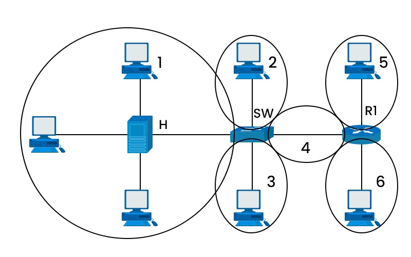
As shown in the picture, you can see the collision domain. Here ‘h’ is the hub, ‘sw’ is a switch, and R1 is the router. We can see that there is a single collision domain in the case of the hub, whereas separate collision domains exist in the case of the router and switch. Here are the differences between hub, switch and router.
Role of Collision Domains in Computer Networks
In the early days of networks, Ethernet networks used to rely on shared communication channels. So, it was necessary to manage collisions to maintain the efficiency of the network. Moreover, before switches were invented or commonly used, the primary devices for networks were hubs. Hubs were not capable of differentiating between various devices, causing more frequent collisions.
How Does Collision Domain Work?
In a shared network, devices take turns to send data. However, if two devices send data together, a collision occurs, which will cause delays. In half-duplex systems, devices can either send or receive data at any given time, not both. This limitation increases the chances of collisions.
Ethernet networks use CSMA/CD to identify any collisions and recover from them. It ensures that the data is eventually transmitted successfully.
Factors Affecting Collision Domains
Collisions happen when two or more devices on a shared network medium try to send data simultaneously. The shared medium can be a wire, a cable, or a wireless channel. Some of the factors that affect collision are:
- Number of devices connected to a network: The more devices connected to a network, the higher the chances of collisions. Similarly, the longer the network cable, the more time it takes for the data to travel from one end to another, increasing the possibility of collisions.
- Speed of data transmission: The speed of data transmission also affects the collision rate, as faster speeds require more bandwidth and result in more collisions.
- Type of network device: The type of network device used to interconnect network segments can either increase or decrease the size and number of collision-domains. For example, hubs and repeaters are simple devices that amplify and forward signals from one segment to another without any filtering or processing. They do not divide or isolate collision-domains but rather extend them.
Characteristics of Collision Domain
- Shared bandwidth: All devices in the domain share the same bandwidth. Therefore, during high usage, the speed gets slow.
- Impacts Network Performance: If there are more devices in the domain, the chances of collisions also increase. So, there is a high chance of network slowdown.
How do different devices handle Collision Domains?
- Hubs: Hubs broadcast data to all connected devices, creating large domains, which increases the risks of collisions.
- Switches: Switches divide collision domains into many parts, where each device has its own domain. This reduces the chances of collisions.
- Routers: Routers implement segmentation into the network, creating multiple broadcast domains. This ensures efficient data flow.
How to Minimize Collision Domains?
To avoid or minimize collision domains in a network, several strategies can be implemented, such as:
Router
In previous network environments, where half-duplex was commonly used, or full-duplex was not possible, the deployment of routers emerged as the initial approach to address collisions.
While it may not entirely eliminate the issues, implementing this solution would significantly reduce their impact. During that period, switches were known for their high cost. Routers are cost-effective as compared to switches. Introducing routers into a topology with the sole purpose of dividing collision domains can be a challenging task. But today, there exist other alternatives also.
Switches and Full Duplex
Switches create separate domains for each port, meaning that only devices connected to the same port can collide with each other. Devices connected to different ports do not interfere with each other’s transmissions, as switches forward packets only to their intended destinations.
Switches also support full-duplex mode, which allows devices to send and receive data simultaneously without collisions. The full-duplex mode requires two pairs of wires for each connection, one for sending and one for receiving.
Using wireless networks instead of wired networks
Using wireless networks instead of wired networks eliminates collision-domains altogether by using a different MAC protocol called Carrier Sense Multiple Access with Collision Avoidance (CSMA/CA). CSMA/CA works similarly to CSMA/CD, but instead of detecting collisions, it avoids them by using a mechanism called Request-to-Send/Clear-to-Send (RTS/CTS). Here are the differences between CSMA CD and CSMA CA.
Avoid channel saturation
In the case of wireless networks, because of channel saturation, a lot number of collisions can occur. Many nodes using the same communication channel increase the possibility of collision between them. In order to limit the collision domain, it is crucial to have an adequate number of access points distributed over non-overlapping channels.
Difference between Broadcast Domain and Collision Domain
Definition
- Collision Domain: A network segment in which data segments can collide with each other if sent simultaneously.
- Broadcast Domain: It is a portion of the network where broadcast packets are forwarded to all devices connected to the network.
Impact of Devices
- Collision Domain: It reduces the efficiency of a network because of the retransmission of data after collisions. It is most common in Hubs.
- Broadcast Domain: It can cause network congestion, but only if the broadcast domain is very large because every device in the broadcast domain will process broadcasts.
Examples
- Collision Domain: Two devices connected through a hub are in a collision domain.
- Broadcast Domain: All devices within the same VLAN are part of the same broadcast domain.
Advantages of Collision Domain
- Improved troubleshooting skills.
- Network performance optimization.
- It can increase your understanding of network segmentation.
- Makes it easier to locate network faults in a segment.
- It helps reduce collisions when domains are kept small and controlled.
- Improves bandwidth for each device in its own domain.
- Supports cleaner network segmentation and design.
- Enhance security by limiting where traffic can spread.
- Aids in capacity planning and future network upgrades.
Disadvantages of Collision Domain
- Limited scalability in shared networks.
- Compatibility challenges with newer technologies.
- More data collisions occur when many devices share the same medium.
- Lower network throughput because frames must be retransmitted after collisions.
- Higher delay and jitter, which hurts voice and video traffic.
- More complex troubleshooting in large flat networks that use hubs.
- Poor scalability, as adding devices increases collision chances.
- More devices are affected by one fault on a shared segment.
Frequently Asked Questions
Q1. What is collision domain and broadcast domain?
The collision-domain refers to a specific network segment that allows bidirectional traffic transmission. A broadcast domain refers to a certain sort of domain in which network traffic circulates over the whole network.
Q2. Is hub a collision domain?
A hub is neither a collision domain nor a broadcast domain.
Q3. What are collision domain examples?
Switches are another common example of a collision domain in use. Each port on a switch represents a potential collision-domain. In simple words, a switch’s collision domain count is proportional to the number of ports it has. A switch with 24 ports has 24 possible collision domains.
Q4. What is the OSI layer collision domain?
The OSI layer that defines the collision-domain is the “data link layer”, i.e., layer 2, which is responsible for the physical and logical transmission of data between nodes on a network.
Q5. Is a VLAN a collision domain?
No, VLANs create broadcast domains, not collision domains. Collision domains rely on physical Ethernet segments and ports of switches or hubs, whereas VLANs are logically grouping their devices in network segments.
Conclusion
Collision-domains are network segments where only one device can transmit data at a time. It is an important concept to understand for network design and troubleshooting. By knowing what is collision domain, what are the factors that affect them, and how to avoid or minimize them, you can optimize your network performance and reliability.
Difference between Broadcast Domain and Collision Domain
1. Collision Domain (Explanation)
A collision domain is a network area where multiple devices share the same medium, and if two devices send data at the same time, a collision occurs. It mainly happens in networks using hubs or shared Ethernet.
👉 Example:
If 4 computers are connected to a hub, all devices are in one collision domain. If PC1 and PC2 send data at the same time, a collision happens.
2. Broadcast Domain (Explanation)
A broadcast domain is a network area where a broadcast message (data sent to all devices) is received by every device in that network segment. Broadcast traffic is used for communication like ARP requests.
👉 Example:
If 10 computers are connected to a switch, all devices will receive a broadcast message (like ARP). So, all 10 devices are in one broadcast domain.
3. Key Differences (Table Format)
| Feature | Collision Domain | Broadcast Domain |
|---|---|---|
| Definition | Area where data collisions can occur | Area where broadcast packets are received |
| Problem | Data collision | Broadcast traffic flooding |
| Device Impact | Affects devices sending at same time | Affects all devices in network |
| Works In | Half-duplex / shared networks | All Ethernet networks |
| Broken By | Switch, Bridge | Router |
| Hub Behavior | One collision domain | One broadcast domain |
| Switch Behavior | Each port = separate collision domain | Entire switch = one broadcast domain |
| Router Behavior | Each interface = separate collision domain | Each interface = separate broadcast domain |
4. Practical Example
Network with Hub:
- 5 PCs connected to a hub
- Collision Domain = 1
- Broadcast Domain = 1
👉 Collisions happen frequently.
Network with Switch:
- 5 PCs connected to a switch
- Collision Domain = 5 (one per port)
- Broadcast Domain = 1
👉 No collisions, but broadcasts still reach all devices.
Network with Router:
- 2 switches connected via router
- Each switch has 5 PCs
- Collision Domain = Multiple (per port)
- Broadcast Domain = 2 (router separates)
👉 Broadcast is limited to each network.
5. Simple Real-Life Analogy
- Collision Domain = People talking in one room → If 2 talk at same time = confusion
- Broadcast Domain = Announcement in a room → Everyone hears it
Conclusion
- Collision Domain deals with data collisions (solved by switches).
- Broadcast Domain deals with broadcast traffic (controlled by routers).