
ARP Protocol
ARP Role
Address Resolution Protocol (ARP) is a very fundamental protocol in computer networking. When a PC wants to send a message over the network, it has to encapsulate the data down the layers of the OSI model. At each layer, it has to fill all header information such as TCP/UDP ports in the layer 4 header, source, and destination IP addresses in the Layer 3 header, and source and destination MAC addresses in the Layer 2 header. If you think about it, all this information is available to the end client except for the destination MAC address. Address Resolution Protocol (ARP) has been introduced to resolve a MAC address based on a given IP address in a local network.
Let’s look at the example shown in Figure 1.
PC1 tries to ping PC3, which is in the same local area network and the same subnet 10.1.1.0/24. When the user executes the command ping 10.1.1.3, PC1 starts encapsulating an ICMP Request (ping) into an Ethernet frame before sending it over the network. Let’s look at how PC constructs the protocol data unit (PDU):
- At the application layer – PC1 knows that ping works by sending an ICMP Echo Request and waits for an ICMP Echo Response. So, it sets the protocol to be ICMP with the Echo Request flag set. Therefore, everything needed at this layer is available.
- At layer 3 – PC1 knows the destination IP address, it is explicitly mentioned by the user in the ping 10.1.1.3 command so it puts it into the destination IP field. PC1 knows its own configured IP address 10.1.1.1 and puts it in the source field. Therefore, everything needed at this layer is available.
- At later 2 – PC1 knows its own configured MAC address and put in the source field. BUT there is no way for PC1 to know which end client in the LAN has 10.1.1.3 configured and what is its MAC address. Therefore destination MAC address is not available to PC1 and it has to use ARP in order to get it.
How ARP works
ARP uses broadcast communication (one-to-all) in order to ask all end clients within a LAN, what is the physical address of a given IP.
ARP Messages
There are two main types of packets in ARP operations:
- ARP Request
- ARP Reply
Figure 2 shows an example of both types. You can see that there are four fields in the ARP header:
- Source Hardware Address (MAC)
- Source Protocol Address (IP)
- Target Hardware Address (MAC)
- Target Protocol Address (IP)
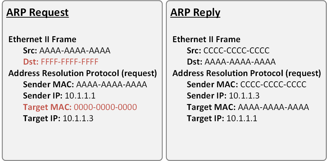
Note that in the ARP Request message, the destination MAC address is the well-known broadcast address FFFF-FFFF-FFFF. This signals the switches in the LAN that this is broadcast communication and all connected devices in the LAN must receive a copy of the frame. The other important value to note is the Target MAC is 0000-0000-0000. This signals the owner of the Target IP that the sender is trying to resolve the physical address of this IP.
Note that in the ARP Reply messages, both source and destination MAC addresses are unicast ones.
There are four typical cases when this happens:
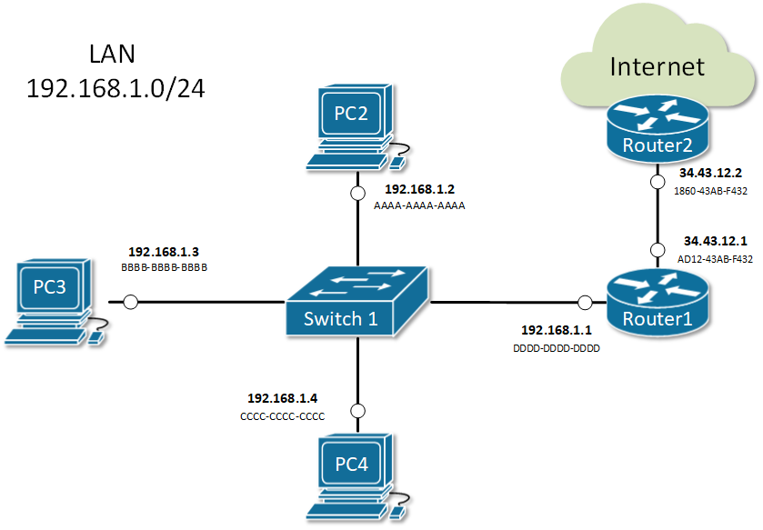
- Host wants to send data to another host in the same network. For example, PC2 sends a message to PC3.
- PC2 sends an ARP request about the IP address of PC3 192.168.1.3.
- Everybody on the LAN receives a copy of the ARP frame.
- PC3 replies back with its physical address BBBB-BBBB-BBBB. All other hosts drop the ARP request.
- Host wants to send data to another host in another network. For example, PC2 sends a message to google.com.
- PC2 looks at its routing table.
- Finds the IP address of its default gateway 192.168.1.1.
- Sends an ARP request about the default gateway IP address 192.168.1.1.
- Everybody on the LAN receives a copy of the ARP frame including Router1.
- Router1 replies back with its physical address DDDD-DDDD-DDDD.
- A router receives data destined for a host in a locally connected network. Router1 receives data destined for PC2.
- Router 1 sends an ARP request about the destination IP address 192.168.1.2.
- Everybody on the LAN receives a copy of the ARP frame.
- PC2 replies back with its physical address. All other hosts drop the ARP request.
- A router receives data destined for a host on another network. Router2 receives data destined for PC2.
- Router2 checks its routing table.
- Finds that the next-hop address towards PC2 is 34.43.12.1.
- Sends an ARP request about the next-hop IP address 34.43.12.1.
- Router1 receives a copy of the ARP request.
- Router1 replies back with its physical address AD12-43AB-F432.
ARP Table (ARP Cache)
When a device successfully resolves the MAC address of a given IP, it stores the IP-to-MAC binding in a table called the ARP table. Subsequent communication use this cached binding instead of sending ARP request out again. Let’s look at the ARP table of a Cisco router.
					Router#show arp
Protocol  Address          Age (min)  Hardware Addr   Type   Interface
Internet  10.1.1.1                -   00E0.B076.9A02  ARPA   GigabitEthernet0/1
Internet  10.1.1.2                9   0030.A321.43E3  ARPA   GigabitEthernet0/1
Internet  192.168.1.1             -   00E0.B076.9A01  ARPA   GigabitEthernet0/0
Internet  192.168.1.2             23  0040.0BAD.3852  ARPA   GigabitEthernet0/0
Internet  192.168.1.3             59  00E0.F760.8C2D  ARPA   GigabitEthernet0/0
Internet  192.168.1.4             0   00E0.B01D.B1E7  ARPA   GigabitEthernet0/0
Internet  192.168.1.64            2   0060.2FE4.6DB0  ARPA   GigabitEthernet0/0
Each entry in the table is kept for 240 minutes (4 hours) by default. This value is known as ARP Timeout and can be set to a different value per interface. You can check it by a look at the output of show interface.
					Router#sh int GigabitEthernet 0/1
GigabitEthernet0/0/1 is up, line protocol is up (connected)
  Hardware is ISR4331-3x1GE, address is 00e0.b076.9a02 (bia 00e0.b076.9a02)
  Internet address is 10.1.1.1/24
  MTU 1500 bytes, BW 1000000 Kbit, DLY 100 usec,
     reliability 255/255, txload 1/255, rxload 1/255
  Encapsulation ARPA, loopback not set
  Keepalive not supported
  output flow-control is on, input flow-control is on
  ARP type: ARPA, ARP Timeout 04:00:00,
  Last input 00:00:08, output 00:00:05, output hang never
  Last clearing of "show interface" counters never
  Input queue: 0/375/0 (size/max/drops); Total output drops: 0
  Queueing strategy: fifo
  Output queue :0/40 (size/max)
  5 minute input rate 4 bits/sec, 0 packets/sec
  5 minute output rate 4 bits/sec, 0 packets/sec
     4 packets input, 512 bytes, 0 no buffer
     Received 0 broadcasts (0 IP multicasts)
     0 runts, 0 giants, 0 throttles
     0 input errors, 0 CRC, 0 frame, 0 overrun, 0 ignored
     0 watchdog, 1017 multicast, 0 pause input
     0 input packets with dribble condition detected
     4 packets output, 512 bytes, 0 underruns
     0 output errors, 0 collisions, 1 interface resets
     0 unknown protocol drops
     0 babbles, 0 late collision, 0 deferred
     0 lost carrier, 0 no carrier
     0 output buffer failures, 0 output buffers swapped out
The ARP Cache of hosts running Windows or Unix can be checked by executing arp -a in the command prompt window
					C:\>arp -a
  Internet Address      Physical Address      Type
  192.168.1.1           00e0.b076.9a01        dynamic
  192.168.1.2           0040.0bad.3852        dynamic
  192.168.1.4           00e0.b01d.b1e7        dynamic
  192.168.1.64          0060.2fe4.6db0        dynamic
Summary
- Address Resolution Protocol (ARP) is a mechanism to resolve the physical address (MAC) of a given logical address (IP) in a LAN: IP-to-MAC binding.
- An ARP Request is encapsulated in a broadcast frame. Therefore, it is one-to-all communication and every host in the LAN receives a copy of the ARP request. Only the owner of the targeted IP replies back.
- An ARP Reply is encapsulated in a unicast frame. Thus it is a one-to-one communication between the requestor and the replier.
- When a device receives the physical address of an IP, it creates an entry in its ARP Table (ARP Cache). Any subsequent communication uses the cached entry.
- Every entry in the ARP table is kept for 4 hours by default. This is called ARP Timeout.
ARP Features
Static ARP Entries
Static ARP entry is a permanent IP-to-MAC binding in the ARP table (ARP cache). One reason that you may want to do this is if two nodes in the LAN are constantly communicating and never change their IP and MAC addresses. Another reason would be to prevent the ARP entry from being overridden by a rouge host in the LAN. In some advanced network scenarios, an IP may need to be bind to a multicast MAC address which can only be done with static ARP.
To add a static ARP cache entry on a Cisco device we use the following command.
R1(config)#arp 192.168.1.5 20fc.1480.aff2 arpa
To add a static ARP cache entry on a Windows machine we use the following command.
C:\> arp -s 192.168.1.10 48-6d-bb-be-a6-66
After executing this command, we can see that the IP-to-MAC binding is in the ARP table
					C:\>arp -a
Interface: 192.168.1.104 --- 0x10
  Internet Address      Physical Address      Type
  192.168.1.1           54-e6-fc-b6-cb-40     dynamic
  192.168.1.101         48-6d-bb-be-a6-66     dynamic
  192.168.1.10         48-6d-bb-be-a6-66     static
  192.168.1.255         ff-ff-ff-ff-ff-ff     static
Gratuitous ARP (GARP)
Gratuitous ARP is an unsolicited message used when a host wants to tell all other nodes to update theirs ARP cache with new MAC-to-IP binding. An example of such a use-case would be when the IP address of a client is suddenly changed. Let’s look at the example in Figure 1. Initially, PC1 has IP address 10.1.1.1 and has been communicating over the network for some time. Therefore Router 1 has an entry in the ARP table for PC1’s IP-to-MAC binding (10.1.1.1 AAAA-AAAA-AAAA).
But what happens if suddenly, the IP address of PC1 is changed from 10.1.1.1 to 10.1.1.7? There is no way for the other nodes in the LAN including Router 1 to know that. So in the ARP cache of router 1 nothing would change until the entry 10.1.1.1 AAAA-AAAA-AAAA expires in 4 hours, but until then communication between PC1 and Router 1 would not be possible.
Gratuitous ARP has been introduced to solve this problem. When the IP address of PC1 is changed. It immediately sends out a GARP message that tells all nodes in the LAN to update their MAC-to-IP bindings with the new address 10.1.1.7 AAAA-AAAA-AAAA. Note that the message is sent unsolicitedly (without ARP Request )
Proxy ARP
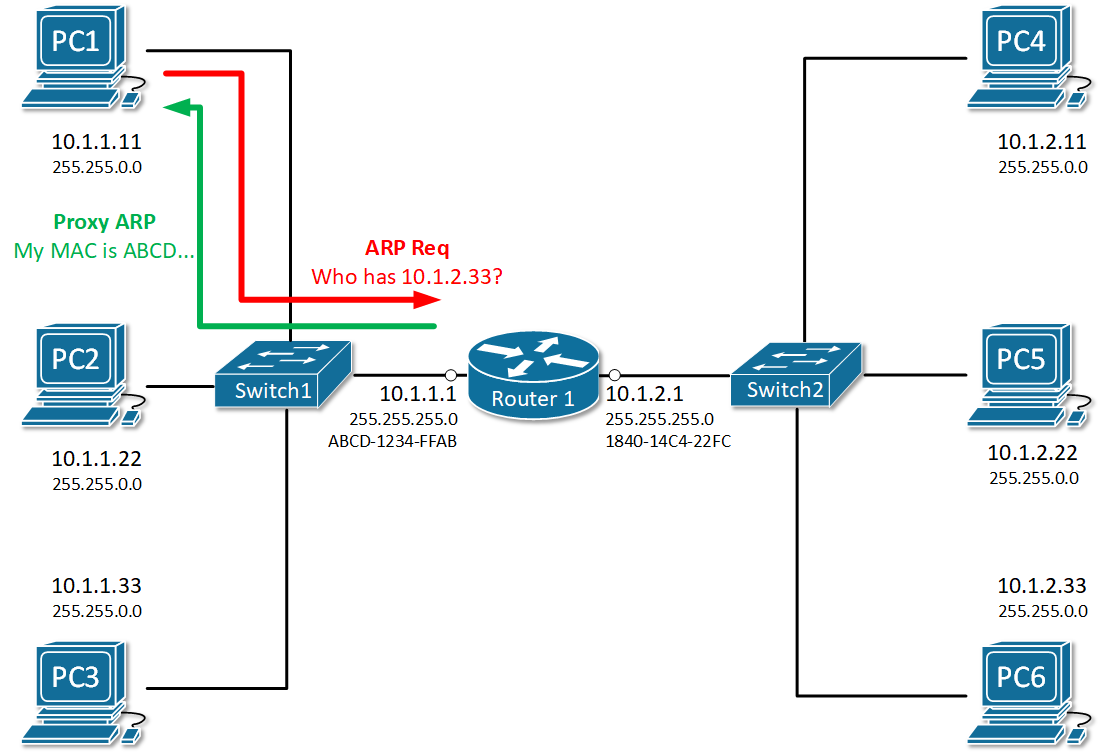
Proxy ARP is a technique by which a router answers with its own MAC address to ARP requests for an IP address that is not on the local network. The router, acting as a proxy, must have a valid route in the routing table for the traffic’s destination. A typical scenario when proxy ARP is used is called Transparent subnet gatewaying. This is the case when two separate data-link segments (two different broadcast domains) use the same IP range as shown in Figure 2. In this example, PC1, PC2, and PC3 are in one data-link segment and PC4, PC5, and PC6 are in a different one. Think what will happen when PC1 wants to communicate with PC6, it will send an ARP request such as “Who has 10.1.2.33” but will PC6 ever hear that ARP request in order to reply back? No, it won’t because both hosts are in different broadcast domains and the ARP frame from PC1 won’t reach PC6. By default, on all Cisco routers, there is a feature called Proxy ARP, which is enabled on all Layer 3 interfaces. It has been introduced to solve this problem by replying to ARP requests for IP addresses that the router has routing towards. In our sample, Router 1 will reply to the ARP request of PC1 with its own MAC address ABCD-1234-FFAB and when the actual traffic comes, it will route to PC6. Ultimately, PC1 and PC6 won’t even understand that there is a router in between them, that is why this scenario is called Transparent subnet gatewaying.
To check whether Proxy ARP is enabled on an interface, we use the show ip interface <interface number> command
					R1#sh ip interface gi0/0/0
GigabitEthernet0/0/0 is up, line protocol is up (connected)
  Internet address is 10.1.1.1/24
  Broadcast address is 255.255.255.255
  Address determined by setup command
  MTU is 1500 bytes
  Helper address is not set
  Directed broadcast forwarding is disabled
  Outgoing access list is not set
  Inbound  access list is not set
  Proxy ARP is enabled
  Security level is default
  Split horizon is enabled
  ICMP redirects are always sent
  ICMP unreachables are always sent
  ICMP mask replies are never sent
  IP fast switching is disabled
  IP fast switching on the same interface is disabled
  IP Flow switching is disabled
  IP Fast switching turbo vector
  IP multicast fast switching is disabled
  IP multicast distributed fast switching is disabled
  Router Discovery is disabled
  IP output packet accounting is disabled
  IP access violation accounting is disabled
  TCP/IP header compression is disabled
  RTP/IP header compression is disabled
  Probe proxy name replies are disabled
  Policy routing is disabled
  Network address translation is disabled
  BGP Policy Mapping is disabled
  Input features: MCI Check
  WCCP Redirect outbound is disabled
  WCCP Redirect inbound is disabled
  WCCP Redirect exclude is disabled
To disable the feature an interface, we use no ip proxy-arp command in interface configuration mode.
					R1# configure terminal
Enter configuration commands, one per line.  End with CNTL/Z.
R1(config)# interface gi0/0/0
R1(config-if)# no ip proxy-arp
R1(config-if)# ^Z
R1#
Inverse ARP
As the name implies, inverse ARP is used to find a Layer-3 address (IP address) based on known Layer 2 address (typically DLCI in frame relay and ATM). In frame relay, for example, the remote router’s DLCI is known but its IP address is not known. Therefore Inverse ARP is used to obtain and map the Layer 2 DLCI-to-IP.
As Frame-Relay slowly disappeared, Inverse ARP is not commonly used anymore.
Reverse ARP
Reverse ARP was used for requesting an IP address from the gateway router’s ARP table. It is a predecessor of two common protocols – BOOTP (Bootstrap Protocol) and DHCP (Dynamic Host Configuration Protocol). It is not used anymore in modern local area networks.
Summary
- Static ARP entry is a permanent IP-to-MAC binding in the ARP table configured manually by a network administrator. A typical use-case is to enhance local area security between certain hosts that do not change their IP addresses often.
- Gratuitous ARP is an unsolicited message used when a host wants to tell all other nodes to update theirs ARP cache with new MAC-to-IP binding.
- Proxy ARP is used when a router replies to an ARP request for an IP address that is not part of the local network. The proxy (the router) must have a valid route to the destination in the routing table.
- Inverse ARP is used to find a Layer-3 address (IP address) based on known Layer 2 address (typically DHCP). Not commonly used anymore.
- Reverse ARP is used for requesting an IP address from the gateway router’s ARP table. Not used anymore because we have BOOTP and DHCP.
ARP Security
ARP vulnerabilities
Address Resolution Protocol (ARP) has been designed in times when network security has not been very developed. Therefore the protocol is clear text with no embedded security. It does not validates ARP packets and even accepts ARP Response even if ARP Request has never been sent out. By default, no mechanism validates whether a rouge host sends malicious ARP messages or intercepts and alters ARP Request/Replies. Several well-known attacks use the same process called ARP spoofing. The ultimate goal of the attackers is to get in the data path, as shown in Figure 1, and steal private data.
ARP spoofing
When a rouge host in the local area network sends false ARP messages, it can associate its MAC address with the IP address of the default gateway or any other IP in the LAN. It then can start receiving data intended for another host in the network. There are there main attacks that utilize this spoofing technique:
- Main-in-the-Middle: An intruder intercepts ARP messages from legitimate users and modifies them to redirect the data.
- Session Hijacking: A hacker tries to use ARP spoofing to steal a cookie, token, or session ID so he can gain unauthorized access to private data. Pretty common in public WiFi networks at busy bus stations and airports.
- Denial of Service (DoS): An attacker tries to make a host or network resource unavailable to its intended users. Typically in the case of ARP spoofing, it is done by stealing legitimate data intended to the particular host or flooding the host with a high number of false or malformed ARP messages.
Let’s look at the example in Figure 2. PC1 sends an ARP Request for the IP of Router 1. As you already know, all nodes in the LAN receive a copy of this packet. Because of that, an attacker with IP 192.168.1.6 can spoof or alter the reply of router 1 in a way so the physical address associated with IP 192.168.1.1 is 5445-CCCD-DDDD. This will force all traffic between PC1 and Router 1 to go through the attacker as shown in Figure 1. This type of ARP exploit is often referred to as ARP Poisoning.
ARP Security Features
Cisco has introduced a few ARP security features to address the vulnerabilities explained above.
Dynamic ARP Inspection (DAI)
Dynamic ARP inspection (DAI) is a feature that intercepts ARP Request/Reply messages and validates the MAC-to-IP bindings against a trusted database built by another feature called DHCP snooping. The main idea is that if you dynamically assign IP addresses to hosts with DHCP, the switch can snoop the DHCP messages and track which IP is given to which host in the LAN. Based on that information, it can, later on, validate if a host replies to ARP request for an IP address that is not assigned to it. Invalid or false ARP replies are dropped.
The feature works by associating a trust state to each interface on the switch. ARP frames arriving at trusted interfaces bypass the inspection, while those being received on untrusted ports go through a validation check. In a typical DAI configuration, all switch ports connected to end clients would be untrusted, while the ports connected to other switches/routers or DHCP servers would be trusted.
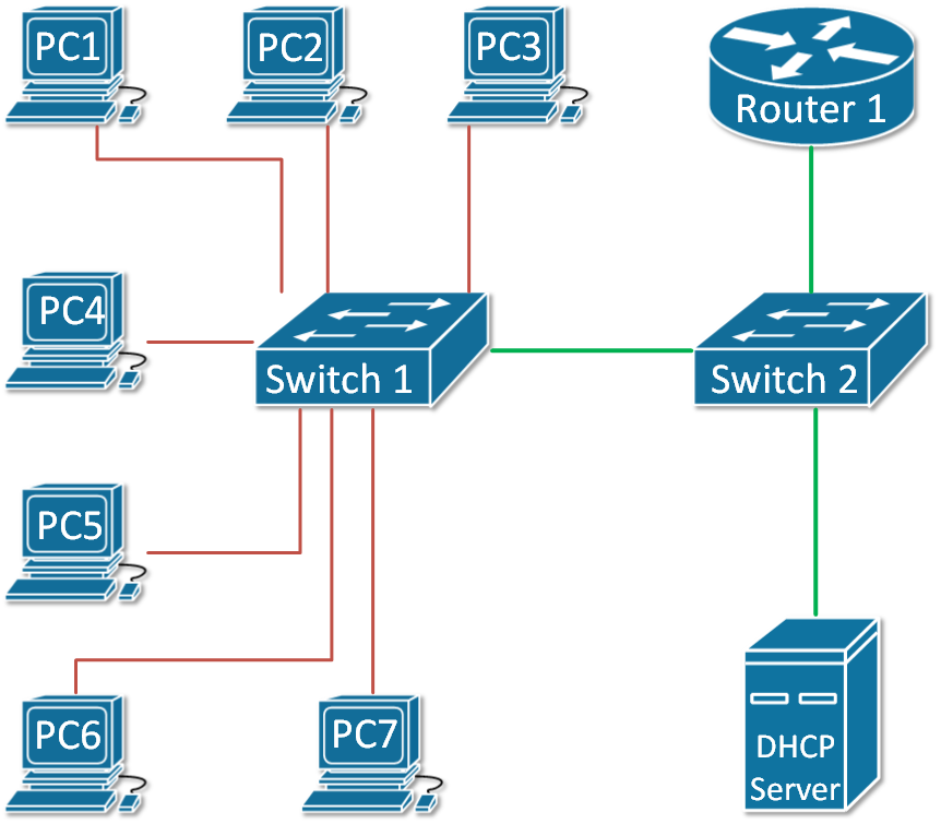
Let’s look at the example in Figure 3. The green ports are configured as trusted and the red ones are untrusted.
ARP Rate Limiting
ARP packets are processed in the CPU, so when a switch receives a high number of ARP frames, this can easily overload the CPU and crash the device. This can be exploited as a denial-of-service attack. DAI has a built-in mechanism that prevents this by limiting the number of ARP packets that can go to the CPU each second. When dynamic ARP inspection is enabled on a switch, automatically all untrusted ports are rate-limited to 15 ARP packets per second, while trusted has no rate-limiting. When the rate of incoming ARP frames exceeds the limits, the interface is disabled.
DAI Logging
A log message is generated for every denied ARP packet and can be sent to Security Operation Center (SOC) for analysis or can be fed into automated threat detection algorithms that can act upon it. An example of such a log message is shown below.
14:21:58: %SW_DAI-4-DHCP_SNOOPING_DENY: 1 Invalid ARPs (Req) on Gi1/0/21, vlan 1.([18b1.a4f5.3aa1/192.168.1.45/0000.0000.0000/0.0.0.0/14:14:21 UTC Fri June 12 2020])
Configuring Dynamic ARP Inspection (DAI)
Assume we are using the topology shown in Figure 3 as an example. To enable Dynamic ARP Insepction (DAI) on both switches and configure the trunk link between as trusted, the following steps are needed:
Step 1: Enabling and Verifying DAI on both switches.
					SW1#configure terminal
Enter configuration commands, one per line.  End with CNTL/Z.

SW1(config)#ip arp inspection ?
  validate  Validate addresses
  vlan      Enable/Disable ARP Inspection on vlans

SW1(config)#ip arp inspection vlan 1
The same configuration is applied on switch 2. Let’s now verify the status of the feature.
					SW1#show ip arp inspection

Source Mac Validation      : Disabled
Destination Mac Validation : Disabled
IP Address Validation      : Disabled
					 Vlan     Configuration    Operation   ACL Match          Static ACL
 ----     -------------    ---------   ---------          ----------
    1     Enabled           Active

 Vlan     ACL Logging      DHCP Logging      Probe Logging
 ----     -----------      ------------      -------------
    1     Deny             Deny              Off

 Vlan      Forwarded        Dropped     DHCP Drops      ACL Drops
 ----      ---------        -------     ----------      ---------
    1              0              0              0              0

 Vlan   DHCP Permits    ACL Permits  Probe Permits   Source MAC Failures
 ----   ------------    -----------  -------------   -------------------
    1              0              0              0                     0

 Vlan   Dest MAC Failures   IP Validation Failures   Invalid Protocol Data
 ----   -----------------   ----------------------   ---------------------
    1                   0                        0                       0
Step 2: Configure the link between the switches as trusted port.
					SW1#sh cdp neighbors
Capability Codes: R - Router, T - Trans Bridge, B - Source Route Bridge
                  S - Switch, H - Host, I - IGMP, r - Repeater, P - Phone
Device ID    Local Intrfce   Holdtme    Capability   Platform    Port ID
SW2          Fas 0/1          170                    3560        Fas 0/1

SW1#configure terminal
Enter configuration commands, one per line.  End with CNTL/Z.

SW1(config)#int fa0/1
SW1(config-if)#ip arp inspection trust
SW1(config-if)#end
SW1#
%SYS-5-CONFIG_I: Configured from console by console

SW1#sh ip arp inspection interfaces fa0/1
Interface        Trust State     Rate(pps)    Burst Interval
---------------  -----------     ---------    --------------
Fa0/1            Trusted                None                 1
Step 3: Verify that DHCP Snooping is running and there are MAC-to-IP Bindings
					SW1# show ip dhcp snooping binding
MacAddress IpAddress Lease(sec) Type VLAN Interface
------------------ --------------- ---------- ------------- ---- --------------------
18:50:FD:3D:4C:01 192.168.1.7 5227 dhcp-snooping 1 FastEthernet0/7
Now lets see what will happen if a rouge host sends a false ARP reply trying to poison the ARP cache for 192.168.1.7
14:21:41: %SW_DAI-4-DHCP_SNOOPING_DENY: 2 Invalid ARPs (Req) on Fa0/7, vlan 1.([1841.0fc2.043d/192.168.1.7/0000.0000.0000/0.0.0.0/14:20:35 UTC Tue June 12 2020])
Summary
- ARP is not a secure protocol and doesn’t have built-in security mechanisms.
- A few exploits based around ARP Spoofing (ARP Poisoning) are well-known.
- Cisco has introduce a feature called Dynamic ARP Inspection (DAI) that mitigates most of the well-know vulnarabilities.
- DAI depends on another feature called DHCP Snooping that tracks which IP address has been given by DHCP to which host and store that information in a MAC-to-IP binding table.
- DAI works by associating a trust state to each interface on the switch. When ARP packet arrives on untrusted port, it is validated against the MAC-to-IP binding table.
- Untrusted ports are rate-limited to 15 ARP packets per second to prevent Denial-of-Service attacks.
What is ARP
What is ARP (Address Resolution Protocol)
ARP is a network protocol used to map an IP address (logical address) to a MAC address (physical address) in a local network. In simple terms, when a device knows the IP address of another device but does not know its MAC address, ARP helps to find it. This process is essential because communication inside a LAN (Local Area Network) happens using MAC addresses, not IP addresses.
How ARP Works (Process Explanation)
When a device wants to send data to another device in the same network, it first checks its ARP table (cache) to see if the MAC address of the destination IP is already known. If not, the device sends an ARP Request message to all devices in the network (broadcast). This request says: “Who has this IP address?” The device with the matching IP responds with an ARP Reply (unicast), providing its MAC address. After receiving the reply, the sender stores this mapping in its ARP table and uses it for communication.
Types of ARP Messages
There are mainly two types of ARP messages: ARP Request and ARP Reply. The ARP Request is broadcasted to all devices, while the ARP Reply is sent directly (unicast) to the requesting device. This makes the process efficient after the initial discovery.
Example of ARP
Suppose a computer wants to send data to another device:
- PC1 IP: 192.168.1.10
- PC1 MAC: AA:AA:AA:AA:AA:AA
- PC2 IP: 192.168.1.20
- PC2 MAC: BB:BB:BB:BB:BB:BB
PC1 wants to send data to PC2. It knows the IP (192.168.1.20) but not the MAC. So, PC1 sends an ARP Request:
“Who has 192.168.1.20?”
All devices receive it, but only PC2 replies:
“I am 192.168.1.20, my MAC is BB:BB:BB:BB:BB:BB.”
Now PC1 stores this in its ARP table and sends data directly to PC2 using the MAC address.
Importance of ARP
ARP is very important for network communication because it bridges the gap between Layer 3 (IP address) and Layer 2 (MAC address) of the OSI model. Without ARP, devices would not be able to communicate within a LAN efficiently.
What is RARP
What is RARP (Reverse Address Resolution Protocol)?
RARP is a network protocol used to find the IP address of a device when its MAC address is already known. It works in the opposite way of ARP. While ARP converts an IP address into a MAC address, RARP converts a MAC address into an IP address. It was mainly used by devices that did not have storage to keep their own IP configuration.
Why RARP is Needed
In earlier networks, some devices like diskless workstations did not have hard drives, so they could not store their IP address. When such a device started (booted), it only knew its MAC address. To communicate on the network, it needed an IP address. RARP was used to request an IP address from a RARP server based on its MAC address.
How RARP Works (Process Explanation)
When a device boots up, it sends a RARP Request message to the network (broadcast). This request contains its MAC address and asks: “What is my IP address?” A RARP server listens to this request and checks its database. If it finds a matching MAC address, it sends a RARP Reply (unicast) with the corresponding IP address. The device then uses this IP address to communicate on the network.
Example of RARP
Suppose a device has:
- MAC Address: CC:CC:CC:CC:CC:CC
- IP Address: Unknown
When the device starts, it sends a RARP Request:
“My MAC is CC:CC:CC:CC:CC:CC, what is my IP?”
The RARP server checks its records and replies:
“Your IP address is 192.168.1.30.”
Now the device configures itself with this IP and starts normal communication.
Limitations of RARP
RARP has some limitations. It requires a dedicated RARP server in the same network, and it can only provide IP addresses (not other network details like subnet mask, gateway, etc.). Because of these limitations, RARP is now outdated.
Modern Replacement
RARP has been replaced by more advanced protocols like BOOTP and DHCP. Among them, DHCP is widely used today because it can assign IP address, subnet mask, gateway, DNS, and other configuration automatically.