
Configuring Single-Area OSPF network
Lab Initial State
We use the topology shown in the diagram below. Seven network devices are located at three locations: the data center, large, and small branches.
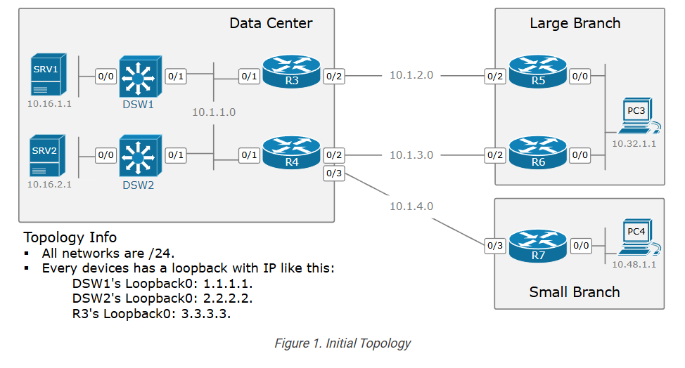
All devices are configured with basic IP settings. All networks are /24 in length. Every device has a configured loopback address that replicates its hostname number. For example, DSW1 has a loopback with address 1.1.1.1, R4 has 4.4.4.4, R7 has 7.7.7.7 and so on. Everything else is by default.
Lab Requirements
We are tasked to configure the network in such a way that it satisfies the following requirements:
- The topology must be fully reachable. All networks must be able to reach each other.
- We must use OSPFv2 with a process ID of 1.
- The entire network must be OSPFv2 Area 0.
- On R7, the OSPFv2 process ID must be 5.
- On R7, it is not allowed to use the network command under the OSPFv2 process.
- Every router must have an explicitly configured Router ID.
- On the shared segment 10.1.1.0/24, DSW1 must be the DR, while DSW2 must be the BDR.
- In the end, PC3 and PC4 must be able to ping both servers – SRV1 and SRV2.
Configuration Workflow
Although designing an OSPF network can be a complex task that requires extensive knowledge and experience, configuring a basic single-area OSPFv2 network can be as easy as entering three commands on each router.
The following diagram outlines the steps required to enable the OSPFv2 process on a router.
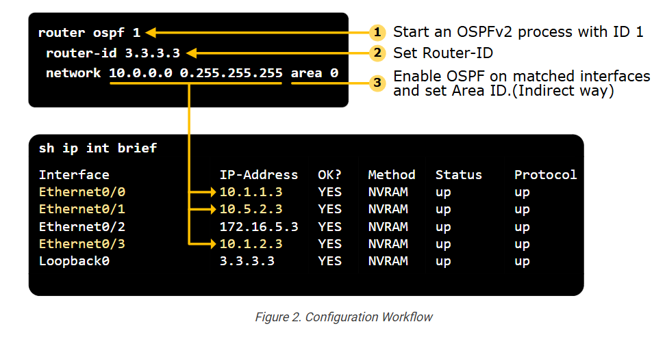
- Step 1. Enable the OSPFv2 process on the device.
- Step 2. Configure a Router ID.
- Step 3. Enable the routing on selected interfaces.
From a configuration point of view, this is pretty much enough to make the routing process work and achieve full IP reachability across the topology. Let’s go through each step in more detail
Step 1. Enabling the OSPF process.
The first step is to enable the OSPFv2 process on the router by defining a process ID. The process ID is a locally significant number between 1 and 65535 (216-1), as shown below.
					DSW1(config)# router ospf ?
 <1-65535>  Process ID
The OSPFv2 process ID is only locally significant to the router. Different routers in the same OSPF network can use different process IDs without affecting their routing protocol operations. However, it is a best practice to use the same process ID across the entire network.
The process ID allows multiple instances of OSPF to run on the same device. Each OSPF instance can be configured independently with its own set of parameters, areas, and interfaces.
In our example, we must configure process ID 1 on all devices except R7, where we must configure process ID 5. Let’s do it.
					! We configrue this on DSW1, DSW2, R3, R4, R5, R6.
DSW1(config)# router ospf 1
DSW1(config-router)#
					! We configrue this on R7.
R7(config)# router ospf 5
R7(config-router)#
Now, we can go to the next step.
Step 2. Specify Router ID (RID)
Once the OSPF process is enabled, the first thing it tries to do is to assign a Router ID (RID). Without a RID, the OSPF process cannot operate.
OSPF uses the following three steps to choose a RID:
- Step 1. First, the router tries to use the explicitly configured RID via the router-id command under the OSPF process.
- Step 2. If the RID isn’t defined explicitly, the router tries to use the highest IPv4 address assigned on a non-shutdown Loopback interface.
- Step 3. If the router cannot assign an RID at step 2, it tries to use the highest IPv4 address on any non-shutdown interface.
Let’s walk through the example shown in the diagram below.
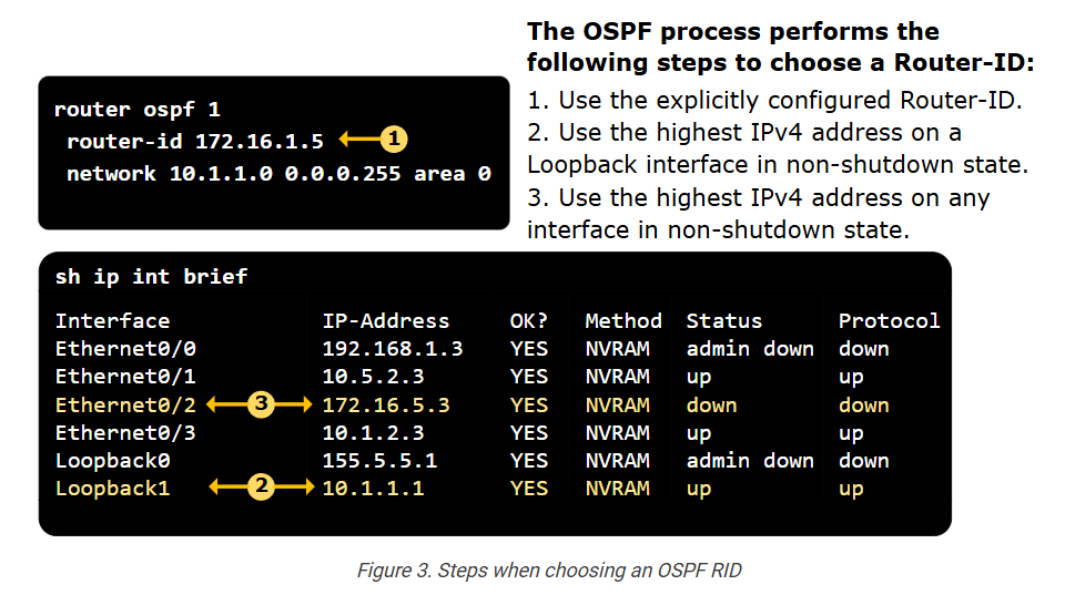
- Since a router-id is configured explicitly under the OSPF process, the router chooses the RID 172.16.1.5.
- If router-id hadn’t been configured, the router would have chosen RID 10.1.1.1 because this is the highest IPv4 address on a Loopback interface that is not shut down.
- Notice that Loopback0 has a higher address but is in an administrative shutdown state.
- If the router hadn’t had loopback addresses, it would have chosen RID 172.16.5.3 because it is the highest IPv4 address on a non-loopback interface that is not shut down. Notice a few important aspects here:
- Eth0/0 has a higher address than Eth0/2 but is shut down.
- Eth0/2 is in a down/down state, but its address is still used as RID since it is not shut down.
You can see that the steps of choosing the RID are fairly simple. However, notice some additional aspects of the process:
- The RID looks like an IPv4 address but it is not! It is simply a 32-bit identifier. The RID doesn’t need to be advertised by the device nor reachable by remote devices.
- When the OSPF restarts, it goes through the steps again and can choose different RIDs if interfaces have changed.
- If a router’s RID changes, all devices in the area must run the SPF because, from the remote router’s perspective, a new RID looks like a new device.
- However, if the RID is explicitly set using the router-id command, the RID never changes. That’s why it is the recommended approach.
Going back to our example, we explicitly configure the RID on all devices as follows:
					DSW1(config)# router ospf 1
DSW1(config-router)# router-id 1.1.1.1
---------------------------------------------
DSW2(config)# router ospf 1
DSW2(config-router)# router-id 2.2.2.2
---------------------------------------------
R3(config)# router ospf 1
R3(config-router)# router-id 3.3.3.3
---------------------------------------------
R4(config)# router ospf 1
R4(config-router)# router-id 4.4.4.4
---------------------------------------------
R5(config)# router ospf 1
R5(config-router)# router-id 5.5.5.5
---------------------------------------------
R6(config)# router ospf 1
R6(config-router)# router-id 6.6.6.6
---------------------------------------------
R7(config)# router ospf 5
R7(config-router)# router-id 7.7.7.7
Step 3. Enable OSPF on selected interfaces
The third step in enabling the OSPFv2 operation on a router is to select the interfaces that will participate in the routing process. But how do we select which interfaces to be OSPF-enabled? There are two ways to enable an interface: directly and indirectly, which is more scalable.
The Network Command (Indirectly selecting interfaces)
Using the network command under the OSPF process indirectly enables the routing process on multiple interfaces. Understanding the network command is key to understanding the OSPFv2 routing.
The network command determines which interfaces will participate in the routing process. It has the following syntaxis:
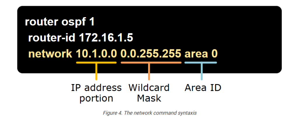
- The IP address portion: This is the IP address of the network you want to include in the routing process. It usually represents a subnet or an interface’s IP address.
- The Wildcard Mask: This mask specifies which bits of the IP address are relevant. It is the inverse of the subnet mask. For example, a subnet mask of 255.255.255.0 (or /24) would correspond to a wildcard mask of 0.0.0.255.
- The Area ID: This specifies the Area in which the matched interfaces should reside.
The network command is all about the wildcard mask. Let’s zoom into it a bit more.
Understanding the Wildcard Mask
In short, the wildcard mask is the inverse of the subnet mask. The OSPFv2 process uses it to determine which bits/octets of the IP address portion to examine for a match.
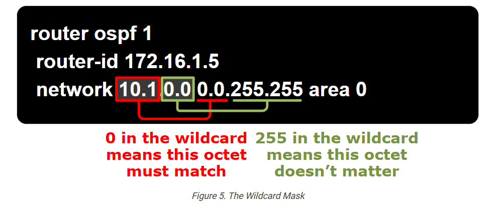
For example, a 0 in the first octet in the wildcard mask means that the first octet in the IP address must match, while a 255 in the wildcard mask means it doesn’t matter.
Examples
Let’s walk through several examples of matching interfaces with different network commands and wildcard masks.
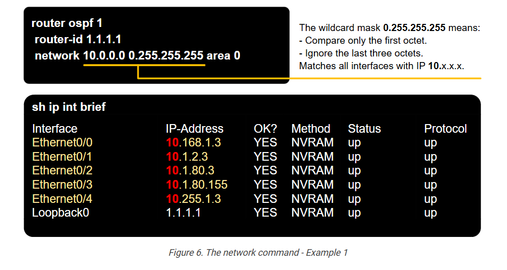
Example 1: We have the command network 10.0.0.0 0.255.255.255 area 0. It matches all interfaces with IP addresses starting with 10.x.x.x, as shown below.
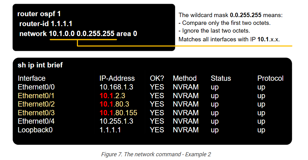
Example 2: We have the command network 10.1.0.0 0.0.255.255 area 0. It matches all interfaces with IP addresses starting with 10.1.x.x, as shown below.
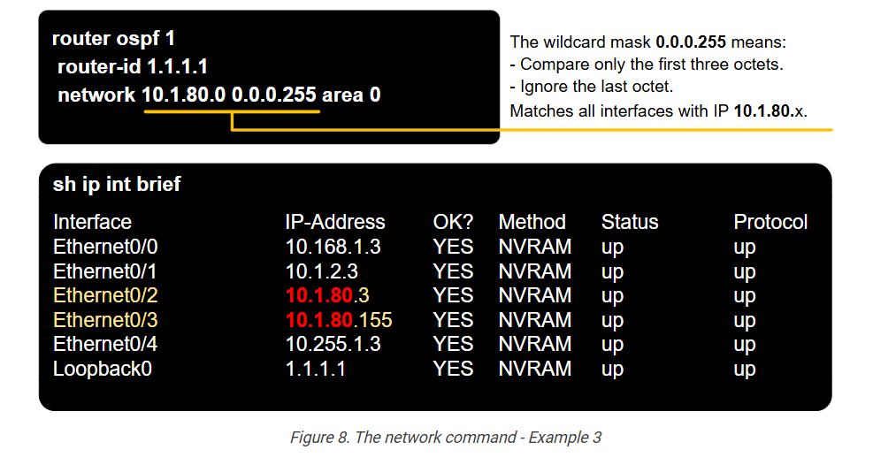
Example 3: We have the command network 10.1.80.0 0.0.0.255 area 0. It matches all interfaces with IP addresses starting with 10.1.80.x, as shown below.
Example 4: We have the command network 10.1.80.155 0.0.0.0 area 0. It matches exactly the interface with IP address 10.1.80.155, as shown below.
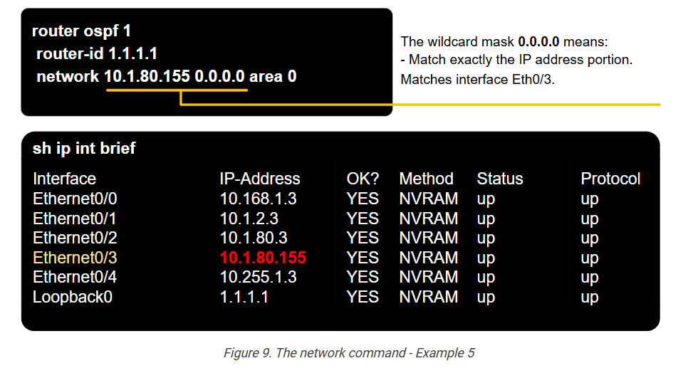
It is very common in production environments to match every interface with an exact match using the wildcat mask 0.0.0.0. This provides the ultimate control over which interfaces are OSPF-enabled. For example, with the interfaces shown in the examples above, to enable the OSPFv2 process on all interfaces, the network commands will look like this:
					router ospf 1
 router-id 1.1.1.1
 network 10.168.1.3 0.0.0.0 area 0
 network 10.1.2.3 0.0.0.0 area 0
 network 10.1.80.3 0.0.0.0 area 0
 network 10.1.80.155 0.0.0.0 area 0
 network 10.255.1.3 0.0.0.0 area 0
 network 1.1.1.1 0.0.0.0 area 0
Every network command enables one particular interface. We have many network commands as interfaces on the device.
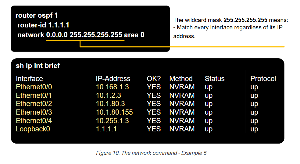
Example 5: We have the command network 0.0.0.0 255.255.255.255 area 0. It matches all interfaces regardless of IP address because every IP matches that wildcard mask, as shown below.
The wildcard mask can be used to match more complex IP address patterns. For example, you can only match odd or even IP addresses, parts of subnet ranges, and so on. However, this is typically never necessary in the network command under the OSPFv2 process. Complex wildcards are generally used in Access Control Lists (ACLs).
In summary, the router uses the network command and the wildcard mask as a tool for matching its own interfaces at scale. The following table summarizes the most used wildcard masks in OSPF.
					IP address	Wildcard Mask	What it does
a.b.c.d	0.0.0.0	Compare all four octets in the IP address portion. Match exactly the IP address a.b.c.d.
a.b.c.d	0.0.0.255	Compare only the first three octets a.b.c.; Ignore the last octet d.
a.b.c.d	0.0.255.255	Compare only the first two octets a.b.; Ignore the last two octets c.d.
a.b.c.d	0.255.255.255	Compare only the first octet a.; Ignore the last three octets b.c.d.
a.b.c.d	255.255.255.255	Match every address.
The Interface Command (Direct selecting interfaces)
There is another way to enable the OSPF process on an interface. You can directly configure the ip ospf [process-id] area [area-id] command under the interfaces on which the routing process must be enabled. For example, we have a router with five physical interfaces, as shown in the example in the figures above. We can enable the OSPFv2 process directly under each interface without using the network command.
					router ospf 1
 router-id 1.1.1.1
 !
interface Ethernet0/0
 ip ospf 1 area 0
 !
interface Ethernet0/1
 ip ospf 1 area 0
 !
...
For the scope of the CCNA, there is no difference between the network command and the interface command to enable the routing process on an interface.
Once the OSPFv2 process is enabled on all interfaces that must participate, the device starts sending Hello packets, forming neighborships, and exchanging the link-state database.
Returning to our example, let’s configure all devices except R7 with the network command. Since all links in our example topology have an IP address that starts with 10.x.x.x, we will use the following network command to enable the routing process on all interfaces.
					! We configrue this on DSW1, DSW2, R3, R4, R5, R6.
! Notice that the loopback IP is different on the different devices.
DSW1(config)# router ospf 1
DSW1(config-router)# network 10.0.0.0 0.255.255.255 area 0
DSW1(config-router)# network 1.1.1.1 0.0.0.0 area 0
As per our requirements, on R7, we must not use the network command, so we will enable the routing process on R7’s Eth0/3 directly under the interface, as shown in the output below. Notice that the OSPFv2 process ID is 5 (and not 1 like on the other devices)
					! We configrue this on R7.
R7(config)# interface Ethernet0/0
R7(config-if)# ip ospf 5 area 0
!
R7(config)# interface Ethernet0/3
R7(config-if)# ip ospf 5 area 0
!
R7(config)# interface Loopback0
R7(config-if)# ip ospf 5 area 0
!
Now, let’s jump into the verification section and see how we verify that the routing protocol is configured and working correctly.
Verifying OSPF Operation
As we saw in the previous section of this course, the OSPF process runs in five main steps:
- Step 1. Enable the OSPF process on the router and select which interfaces to be OSPF-enabled.
- Step 2. Build neighbor relationships with adjacent routers.
- Step 3. Exchange the link-state information until everybody in the area has the same LSDB.
- Step 4. Run the SPF algorithm and find the best paths to every destination in the network.
- Step 5. Update the routing table with the best routes.
The next section of the lesson shows how to display the results of each step of the OSPF process.
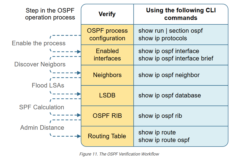
Verification Workflow
The following table shows the verification steps and the CLI command that we can use to check the OSPF operation at each step in the process.
Step 1. Verifying the OSPF Configuration
Typically, when troubleshooting OSPF, it is a good practice to start with the configuration, at least in the beginning. Experienced engineers typically start directly at the OSPF neighbors’ step. However, starting with the config part while studying is more beneficial.
There are two useful commands that help check the OSPF configuration.
- show run | section ospf – Looking at the running config of a router is always useful. You always look for misconfiguration based on your requirements and the topology you work with.
- show ip protocols | section ospf – This command basically repeats the information you can find in the running config, as you can see highlighted in yellow. However, the difference is that you can execute this command from user mode, while the show run command requires enable access.
					DSW1# sh run | s ospf
router ospf 1
 router-id 1.1.1.1
 network 10.0.0.0 0.255.255.255 area 0
 network 1.1.1.1 0.0.0.0 area 0
!
!
DSW1# sh ip protocols | section ospf
Routing Protocol is "ospf 1"
  Outgoing update filter list for all interfaces is not set
  Incoming update filter list for all interfaces is not set
  Router ID 1.1.1.1
  Number of areas in this router is 1. 1 normal 0 stub 0 nssa
  Maximum path: 4
  Routing for Networks:
    10.0.0.0 0.255.255.255 area 0,
    1.1.1.1 0.0.0.0 area 0
  Routing Information Sources:
    Gateway         Distance      Last Update
    4.4.4.4              110      00:01:10
    2.2.2.2              110      00:41:05
    7.7.7.7              110      00:41:10
    6.6.6.6              110      00:41:10
    5.5.5.5              110      00:41:10
  Distance: (default is 110)
Since we have configured R7 differently, the output of both commands is slightly different. In the case of DSW1, we used the network command, and in the case of R7, we used the interface level command. Notice the differences between the outputs of both devices.
					! Notice that there is no network command under the OSPF process configuration.
R7# sh run | s router ospf
router ospf 5
 router-id 7.7.7.7
!
!

! Notice that the OSPF routing is enabled with the interface level command.
R7# sh ip protocols | section ospf
Routing Protocol is "ospf 5"
  Outgoing update filter list for all interfaces is not set
  Incoming update filter list for all interfaces is not set
  Router ID 7.7.7.7
  Number of areas in this router is 1. 1 normal 0 stub 0 nssa
  Maximum path: 4
  Routing for Networks:
  Routing on Interfaces Configured Explicitly (Area 0):
    Ethernet0/0,
    Ethernet0/3
  Routing Information Sources:
    Gateway         Distance      Last Update
    6.6.6.6              110      04:06:38
    4.4.4.4              110      04:06:38
    1.1.1.1              110      04:06:38
    2.2.2.2              110      04:06:38
    5.5.5.5              110      04:06:38
  Distance: (default is 110)
Step 2. Verify the enabled interfaces
The next step is to check the OSPF-enabled interfaces. Generally, you must see all interfaces on the router as OSPF-enabled.
Notice that the command shows the PID, the Area, the IP address, the Mask, and the number of neighbors on each interface.
					DSW1# sh ip ospf interface brief
Interface    PID   Area            IP Address/Mask    Cost  State Nbrs F/C
Lo0          1     0               1.1.1.1/32         1     LOOP  0/0
Et0/1        1     0               10.1.1.1/24        10    DROTH 2/3
Et0/0        1     0               10.16.1.254/24     10    DR    0/0
You can use the following command to see more details about an interface.
					DSW1# sh ip ospf interface ethernet0/1
Ethernet0/1 is up, line protocol is up
  Internet Address 10.1.1.1/24, Interface ID 3, Area 0
  Attached via Network Statement
  Process ID 1, Router ID 1.1.1.1, Network Type BROADCAST, Cost: 10
  Topology-MTID    Cost    Disabled    Shutdown      Topology Name
        0           10        no          no            Base
  Transmit Delay is 1 sec, State DROTHER, Priority 1
  Designated Router (ID) 4.4.4.4, Interface address 10.1.1.4
  Backup Designated router (ID) 3.3.3.3, Interface address 10.1.1.3
  Timer intervals configured, Hello 10, Dead 40, Wait 40, Retransmit 5
    oob-resync timeout 40
    Hello due in 00:00:00
  Supports Link-local Signaling (LLS)
  Cisco NSF helper support enabled
  IETF NSF helper support enabled
  Can be protected by per-prefix Loop-Free FastReroute
  Can be used for per-prefix Loop-Free FastReroute repair paths
  Not Protected by per-prefix TI-LFA
  Index 1/2/2, flood queue length 0
  Next 0x0(0)/0x0(0)/0x0(0)
  Last flood scan length is 1, maximum is 1
  Last flood scan time is 0 msec, maximum is 0 msec
  Neighbor Count is 3, Adjacent neighbor count is 2
    Adjacent with neighbor 3.3.3.3  (Backup Designated Router)
    Adjacent with neighbor 4.4.4.4  (Designated Router)
  Suppress hello for 0 neighbor(s)
Step 3. Verify the neighbors
Showing the OSPF neighbors is the most commonly used command when dealing with OSPF.
					DSW1# sh ip ospf neighbor
Neighbor ID     Pri   State           Dead Time   Address         Interface
2.2.2.2           1   2WAY/DROTHER    00:00:31    10.1.1.2        Ethernet0/1
3.3.3.3           1   FULL/BDR        00:00:32    10.1.1.3        Ethernet0/1
4.4.4.4           1   FULL/DR         00:00:37    10.1.1.4        Ethernet0/1
The output shows several important facts:
- Neighbor ID – The Router ID of the neighbor.
- State – The working state between the local router and the neighbor.
- Address – The neighbor’s IP address on the link.
- Interface – The local router’s interface that comments on that link.
The following table shows what the different neighboring states mean from the point of view of the local router:
| Neighbor State | Description |
| FULL/- | The neighboring state is full. The dash means the link does not use a DR/BDR. (DR/BDR is only used on multiaccess links) |
| FULL/DR | The neighboring state is full. The remote neighbor is the DR. |
| FULL/BDR | The neighboring state is full. The remote neighbor is the BDR. |
| FULL/DROTHER | The neighboring state is full. The remote neighbor is neither the DR nor the BDR. This implies that the local router is a DR or BDR because the state is FULL. |
| 2WAY/DROTHER | The neighboring state is 2-WAY. The remote neighbor is neither the DR nor the BDR. This implies that the local router is also a DROTHER because otherwise, the state would have been full.) |
Notice that according to the neighbor output of DSW1, we can determine that R4 (4.4.4.4) is the DR and R3 (3.3.3.3) is the BDR on the 10.1.1.0/24 segment. This can be further verified by looking at the interface details on DSW1’s link that connects to the segment – Eth0/1. Notice that the local state of DSW1 is DROTHER (meaning it is not the DR nor the BDR). Highlighted further down, you can see that 4.4.4.4 is the Designated Router while 3.3.3.3 is the Backup Designated Router.
					DSW1# sh ip ospf interface eth0/1
Ethernet0/1 is up, line protocol is up
  Internet Address 10.1.1.1/24, Interface ID 3, Area 0
  Attached via Network Statement
  Process ID 1, Router ID 1.1.1.1, Network Type BROADCAST, Cost: 10
  Topology-MTID    Cost    Disabled    Shutdown      Topology Name
        0           10        no          no            Base
  Transmit Delay is 1 sec, State DROTHER, Priority 1
  Designated Router (ID) 4.4.4.4, Interface address 10.1.1.4
  Backup Designated router (ID) 3.3.3.3, Interface address 10.1.1.3
  Timer intervals configured, Hello 10, Dead 40, Wait 40, Retransmit 5
    oob-resync timeout 40
    Hello due in 00:00:04
  Supports Link-local Signaling (LLS)
  Cisco NSF helper support enabled
  IETF NSF helper support enabled
  Can be protected by per-prefix Loop-Free FastReroute
  Can be used for per-prefix Loop-Free FastReroute repair paths
  Not Protected by per-prefix TI-LFA
  Index 1/2/2, flood queue length 0
  Next 0x0(0)/0x0(0)/0x0(0)
  Last flood scan length is 0, maximum is 2
  Last flood scan time is 0 msec, maximum is 0 msec
  Neighbor Count is 3, Adjacent neighbor count is 2
    Adjacent with neighbor 3.3.3.3  (Backup Designated Router)
    Adjacent with neighbor 4.4.4.4  (Designated Router)
  Suppress hello for 0 neighbor(s)
However, according to our lab requirements, we must make DSW1 the DR and DSW2 the BDR. Let’s change the priority of DSW1 to 10 and DSW2 to 5 so that we can satisfy the lab requirements.
					! We change the OSPF priority of DSW1's link on the shared segment to 10
! so that DSW1 can be eligable to become the Designated Router(DR)
DSW1# conf t
Enter configuration commands, one per line.  End with CNTL/Z.
DSW1(config)# int eth0/1
DSW1(config-if)# ip ospf priority 10
DSW1(config-if)# end
-----------------------------------------------------------------
! We change the OSPF priority of DSW2's link on the shared segment to 5
! so that DSW2 can be eligable to become the Backup Designated Router(BDR)
DSW2# conf t
Enter configuration commands, one per line.  End with CNTL/Z.
DSW2(config)# int eth0/1
DSW2(config-if)# ip ospf priority 10
DSW2(config-if)# end
However, recall that there is no preemption with the DR/BDR role! To change the current DR/BDR, you must clear the OSPF process on both routers. Let’s do it.
					R4# clear ip ospf process
Reset ALL OSPF processes? [no]: yes
R4#
------------------------------------------
R3# clear ip ospf process
Reset ALL OSPF processes? [no]: yes
R3#
Now, if we check the neighbors of DSW1, we can see that it is in a FULL state with all others, which implies that the local router is either a DR or BDR. Additionally, since neighbor 2.2.2.2 is obviously the BDR (because the state is FULL/BDR), it implies that DSW1 is the DR.
					DSW1# sh ip ospf neighbor
Neighbor ID     Pri   State           Dead Time   Address         Interface
2.2.2.2           1   FULL/BDR        00:00:33    10.1.1.2        Ethernet0/1
3.3.3.3           1   FULL/DROTHER    00:00:31    10.1.1.3        Ethernet0/1
4.4.4.4           1   FULL/DROTHER    00:00:35    10.1.1.4        Ethernet0/1
There are multiple other ways to confirm which router is the DR and which one is the BDR on the segment. Try it yourself.
If you don’t feel confident with the neighboring states, you can check out this lesson.
If you don’t feel confident with the DR/BDR concept, you can check out this lesson.
Step 4. Verify the LSDB
When a router establishes adjacencies with a neighboring router, it starts exchanging link-state information.
On multiaccess segments like Ethernet VLAN, the router only exchanges its LSDB with the Designated Router (DR).
Since we configured the topology as a single area OSPF, the LSDB must be identical on each router. No matter on which device you execute the command, you must get the same output, as shown in the snippet below.
					DSW1# sh ip ospf database
            OSPF Router with ID (1.1.1.1) (Process ID 1)
                Router Link States (Area 0)
Link ID         ADV Router      Age         Seq#       Checksum Link count
1.1.1.1         1.1.1.1         241         0x8000000A 0x00F6CF 2
2.2.2.2         2.2.2.2         332         0x8000000B 0x00CBEF 2
3.3.3.3         3.3.3.3         305         0x8000000C 0x000D9F 2
4.4.4.4         4.4.4.4         2007        0x8000000E 0x00E37A 3
5.5.5.5         5.5.5.5         295         0x80000008 0x00632E 2
6.6.6.6         6.6.6.6         281         0x80000007 0x005477 1
7.7.7.7         7.7.7.7         1848        0x80000005 0x001CA8 1
                Net Link States (Area 0)
Link ID         ADV Router      Age         Seq#       Checksum
10.1.1.4        4.4.4.4         256         0x80000005 0x00A342
10.1.2.5        5.5.5.5         295         0x80000005 0x006B84
10.1.3.6        6.6.6.6         281         0x80000005 0x008C55
10.1.4.4        4.4.4.4         2007        0x80000003 0x0028C0
In the Router Link State (the router LSA), you must see the Router IDs of all devices in the area.
Step 5. Verify the OSPF RIB and the routing table
The next verification step is to check the device’s IPv4 routing table.
					DSW1# sh ip route
Codes: L - local, C - connected, S - static, R - RIP, M - mobile, B - BGP
       D - EIGRP, EX - EIGRP external, O - OSPF, IA - OSPF inter area
       N1 - OSPF NSSA external type 1, N2 - OSPF NSSA external type 2
       E1 - OSPF external type 1, E2 - OSPF external type 2, m - OMP
       n - NAT, Ni - NAT inside, No - NAT outside, Nd - NAT DIA
       i - IS-IS, su - IS-IS summary, L1 - IS-IS level-1, L2 - IS-IS level-2
       ia - IS-IS inter area, * - candidate default, U - per-user static route
       H - NHRP, G - NHRP registered, g - NHRP registration summary
       o - ODR, P - periodic downloaded static route, l - LISP
       a - application route
       + - replicated route, % - next hop override, p - overrides from PfR
       & - replicated local route overrides by connected
Gateway of last resort is not set
      1.0.0.0/32 is subnetted, 1 subnets
C        1.1.1.1 is directly connected, Loopback0
      10.0.0.0/8 is variably subnetted, 10 subnets, 2 masks
C        10.1.1.0/24 is directly connected, Ethernet0/1
L        10.1.1.1/32 is directly connected, Ethernet0/1
O        10.1.2.0/24 [110/20] via 10.1.1.3, 02:30:36, Ethernet0/1
O        10.1.3.0/24 [110/20] via 10.1.1.4, 02:30:36, Ethernet0/1
O        10.1.4.0/24 [110/20] via 10.1.1.4, 01:50:36, Ethernet0/1
C        10.16.1.0/24 is directly connected, Ethernet0/0
L        10.16.1.254/32 is directly connected, Ethernet0/0
O        10.16.2.0/24 [110/20] via 10.1.1.2, 02:30:31, Ethernet0/1
O        10.32.1.0/24 [110/30] via 10.1.1.3, 02:30:36, Ethernet0/1
O        10.48.1.0/24 [110/30] via 10.1.1.4, 00:07:08, Ethernet0/1
Every router must see an entry in the routing table for every subnet in the network. In small topologies like the one in this example, you can simply count the number of subnets in the topology – eight without the loopback and check if every device has an entry for each subnet.
For example, DSW1 is directly connected only to 10.1.1.0/24 and 10.16.1.0/24, so it must have six more networks learned via OSPF, which is the case (highlighted in blue). However, in large topologies, it is not feasible to count subnets and check large routing tables. You must narrow down what exactly you are troubleshooting and check the data plane instead.
Step 6. Check the Data Plane
The ultimate verification step is always to check whether you have connectivity between the end host. In our example, we check if we can ping the servers (SRV1 and SRV2) from the two end hosts – PC3 and PC4. If the OSPF is configured correctly, we must have full IP reachability between the endpoints.
To check the connectivity, you can use both the ping and traceroute commands.
					PC3# ping SRV1
Type escape sequence to abort.
Sending 5, 100-byte ICMP Echos to 10.16.1.1, timeout is 2 seconds:
!!!!!
Success rate is 100 percent (5/5), round-trip min/avg/max = 1/1/2 ms
--------------------------------------------------------------------
PC3# ping SRV2
Type escape sequence to abort.
Sending 5, 100-byte ICMP Echos to 10.16.2.1, timeout is 2 seconds:
!!!!!
Success rate is 100 percent (5/5), round-trip min/avg/max = 1/1/2 ms
PC4# ping SRV1
Type escape sequence to abort.
Sending 5, 100-byte ICMP Echos to 10.16.1.1, timeout is 2 seconds:
!!!!!
Success rate is 100 percent (5/5), round-trip min/avg/max = 1/1/2 ms
--------------------------------------------------------------------
PC4# ping SRV2
Type escape sequence to abort.
Sending 5, 100-byte ICMP Echos to 10.16.2.1, timeout is 2 seconds:
!!!!!
Success rate is 100 percent (5/5), round-trip min/avg/max = 1/1/2 ms