
Cisco Commnds
Router Basic Commnds
					1.User EXEC Mode
Router>
Commands:
ping
show
traceroute


2.Privileged EXEC Mode
Router#
Commands:
show running-config
reload
debug


3.Global Configuration Mode
Router(config)#
Used to configure the router globally
SSH & Telnet Configuration
1.SSH Authentication For Router Secure Remote Access
....................................................
enable
configure terminal
username saikat secret 123
ip domain-name ksa.com
crypto key generate RSA
line vty 0 4
login local
transport input ssh

SSH Access Any PC CMD Commnd
============================
ssh -l saikat 192.168.1.1


2.Telnet Authentication For Router Remote Access
................................................
enable
configurline vty 0 4
password cisco
logine terminal


Local Telnet Authentication
===========================
username anshuman secret 123
line vty 0 4
login local


Telnet Access Any PC CMD Commnd
===============================
telnet 192.168.1.1
Router Console & Privileged Mode Password Protection Configuration
					1.Router Console Password Protection
.....................................
Set Console Password
====================
configure terminal
line console 0
password cisco
login
exit

OR

username Wise Password set
==========================
configure terminal
username Saikat password 123 (OR) username admin secret admin123
line console 0
login local


2.Encrypt all plain-text passwords
..................................
service password-encryption


3.Privileged Mode Password
..........................
enable secret saikat123
Router Hostname & Login Banner Configuration
					1.Set Hostname of Router
........................
enable
configure terminal
hostname R1


2.Login Banner setup Router
............................
banner motd & Message here &
banner login $ Login Message $
Show Commnds
					Privilege mode
..............
show running-config
show startup-config
show flash
show version
show ip protocols
show hosts
show users
show ip interface brief
show ip interface
Show Interface Status
show ip route
Check Router Firmware & IOS Version
					show version
show flash
dir flash
Delete Router Firmware & IOS
					delete flash://2012546873201mkfd320.bin
show flash
Backup And Restore Router Configuraion File TFTP Server
					1.Router Configuration Backup To TFTP Server
..........................................
Privileged Mode
===============
copy startup-config tftp:
Address or name of remote host []? 192.168.1.100 <Put TFTP Server IP
Destination filename [Router-confg]?Saikat <any name otherwise enter default


2.Router Configuration Backup To TFTP Server
............................................
copy tftp: Address or name of remote host []? 192.168.1.100 <Put TFTP Server IP
Source filename []? saikat-confg <TFTP Server Backup File Name Mention
Destination filename [running-config]? <Enter
Backup And Restore Router IOS Flash Firmware
					1.Router ios Flash Frimware Backup To TFTP Server
.................................................
Privileged Mode
===============
dir flash
show flash
copy flash: tftp:
Source filename []? isr4300-universalk9.16.06.04.SPA.bin <Put file name check show flash
Address or name of remote host []? 192.168.1.100 <Put TFTP Server IP
Destination filename [isr4300-universalk9.16.06.04.SPA.bin]? cisco_ios <Enter New File name Otherwise Defualt Enter


2.Router ios Flash Frimware Restore To TFTP Server
................................................
Privileged Mode
===============
copy tftp: flash:
Address or name of remote host []? 192.168.1.100 <Put TFTP Server IP
Source filename []? cisco_ios <TFTP Server ios Backup File Name Mention
Destination filename [cisco_ios] <Enter
copy run startup-config <Save IOS
reloade
How To IOS Upgrade Process Router
					Upgrading Cisco IOS on a router involves a few key steps to ensure
a smooth transition to a newer version. Here’s a step-by-step guide
for upgrading IOS:
..................................................................

Prerequisites
.............
IOS Image: Download the desired IOS image file from Cisco’s website.
TFTP Server: Set up a TFTP server on your computer.
Console Connection: Connect to the router using a console cable.
Backup: Back up the current configuration.
...........................................

Step-by-Step Upgrade Process
............................
Open a terminal emulator (like PuTTY or Tera Term) and
connect to the router via the console port.


Check Current IOS Version:
..........................
Use the following command to check the current IOS version:

show version

Backup Current Configuration:
.............................
It’s good practice to back up your current configuration:

copy running-config startup-config
copy startup-config tftp


Copy the New IOS Image to the Router:
.....................................

conf t
interface fa0/1
ip address 192.168.1.1 255.255.255.0
no shutdown
exit

copy tftp: flash:

Follow the prompts to enter the TFTP server IP and the filename of the IOS image.


Verify the New IOS Image:
........................
dir flash:


Set the Boot Variable:
Set the router to boot from the new IOS image:
..............................................
conf t
boot system flash flash:<your_ios_image.bin>
exit


Save the Configuration:
Save the updated configuration Commnd
.....................................
write memory


Reboot the Router:
Reload the router to apply the new IOS:
.......................................
reload


Post-Upgrade Checks
...................
show version


Translating "192.168.1.100t"...domain server For Cancel
.......................................................
press Ctrl+Shift+6 to immediately cancel
ping 192.168.1.100 repeat 1000
Installtion New IOS Blank Router
					How to Installing an IOS CISCO Router
.....................................

Prerequisites
.............
Router: Ensure your Cisco router is compatible with the IOS version you plan to install.

IOS Image: Obtain the IOS image file (typically a .bin file).

TFTP Server: Set up a TFTP server on your PC.

Console Cable: Connect your PC to the router via a console cable.
Terminal Emulator: Use a terminal emulator like PuTTY, Tera Term, or HyperTerminal.


Step-by-Step Installation
.........................
Connect to the Router: Use your terminal emulator to connect to the router’s console port.


Enter ROMMON Mode (if necessary):If the router does not boot,
you may need to interrupt the boot sequence
by pressing Ctrl + Break. This will take you to ROMMON mode.


Configure TFTP Settings:In ROMMON mode, set the IP address of the router and the TFTP server


IP_ADDRESS=192.168.1.1          <Router IP Address>
IP_SUBNET_MASK=255.255.255.0    <Router Subnet Mask>
DEFAULT_GATEWAY=192.168.1.254   <Router Gateway Address>
TFTP_SERVER=192.168.1.100       <TFTP Server IP Address>
TFTP_File=iosvbgfjuyng2rrgh.bin <IOS Bin File Path>
tftpdnld                        <Copy the IOS Image Last Commnd>
boot                            <Boot Commnd For IOS To Ram>
Static NAT & Dynamic NAT & Dynamic PAT & DST NAT Port Forwarding
					Static NAT
..........
Configure the router's  Define inside & Outside

interface fa0/0
ip nat outside

interface fa0/1
ip nat inside

ip nat inside source static 192.168.10.10 202.202.10.1
					Dynamic NAT
............
int f0/0
ip nat outside
exit
int f1/0
ip nat inside
exit

ip nat pool saikat 20.1.1.5 20.1.1.20 netmask 255.255.255.0

access-list 1 permit 192.168.1.0 0.0.0.255

ip nat inside source list 1 pool pool1

show ip nat translations
					Dynamic PAT
...........
int f0/0
ip nat outside
exit

int f1/0
ip nat inside
exit

access-list 1 permit 192.168.123.0 0.0.0.255
ip nat inside source list 1 interface fastEthernet 1/0 overload

show ip nat translations

					Port Forwarding Commnds
.......................


WAN Interface
.............
conf t
interface gigabitEthernet 0/0
ip address 50.50.50.1 255.255.255.0
ip nat outside <– Configure the WAN as NAT outside interface
no shutdown
exit


LAN Interface
.............
interface gigabitEthernet 0/1
ip address 192.168.1.1 255.255.255.0
ip nat inside <– Configure the LAN as NAT inside interface
no shutdown
exit


ip route 0.0.0.0 0.0.0.0 50.50.50.2 <– Configure default route

access-list 1 permit 192.168.1.0 0.0.0.255 <– Configure ACL to be used for PAT

ip nat inside source list 1 interface GigabitEthernet0/0 overload <– Configure PAT (NAT overload)


ip nat inside source static tcp 192.168.1.10 80 50.50.50.1 80 <– Port Forwarding for Web Server
ip nat inside source static tcp 192.168.1.11 25 50.50.50.1 25 <– Port Forwarding for SMTP Server

show ip nat translations <---- Checking For NAT Working Or Not
HSRP VRRP GLBP Configuration

					HSRP Configuration
..................

R1
--
interface Ethernet0/1
description LAN Interface of Active Router
ip address 192.168.1.1 255.255.255.0

standby 1 ip 192.168.1.254 <—- Create HSRP Group 1 and assign Virtual IP

standby 1 priority 101 <—- Assign priority above 100 to make this the primary router

standby 1 preempt <—- Makes router active if it has higher priority


R2
--
interface Ethernet0/1
description LAN Interface of Standby Router

ip address 192.168.1.2 255.255.255.0

standby 1 ip 192.168.1.254 <—- Create HSRP Group 1 and assign Virtual IP

standby 1 preempt <—- Makes router active if it has higher priority


VRRP Configuration
.........................

R1
--
interface Ethernet0/1
description LAN Interface of Active Routerip address

ip address 192.168.1.1 255.255.255.0

vrrp 1 ip 192.168.1.254 <—- Create VRRP Group 1 and assign Virtual IP

vrrp 1 priority 101 <—- Assign priority above 100 to make this the primary router

vrrp 1 preempt <—- Makes router active if it has higher priority


R2
..
interface Ethernet0/1
description LAN Interface of Standby Router

ip address 192.168.1.2 255.255.255.0

vrrp 1 ip 192.168.1.254 <—- Create VRRP Group 1 and assign Virtual IP

vrrp 1 preempt <—- Makes router active if it has higher priority


GLBP Configuration
..................

R1
..
interface Ethernet0/1
description LAN Interface of Primary Router

ip address 192.168.1.1 255.255.255.0

glbp 1 ip 192.168.1.254 <—- Create GLBP Group 1 and assign Virtual IP

glbp 1 priority 101 <—- Assign priority above 100 to make this the primary router

glbp 1 preempt <—- Makes router active if it has higher priority

glbp 1 load-balancing round-robin <—- Configure round-robin balancing of traffic


R2
..
interface Ethernet0/1
description LAN Interface of Secondary Router

ip address 192.168.1.2 255.255.255.0

glbp 1 ip 192.168.1.254 <—- Create GLBP Group 1 and assign Virtual IP

glbp 1 preempt <—- Makes router active if it has higher priority

glbp 1 load-balancing round-robin <—- Configure round-robin balancing of traffic
					Additional Commnd
.................

show glbp brief
show glbp

Timers – The default hello timer is 3 seconds. The default hold timer is 10 seconds.

R1(config-if)#glbp 10 timers ?
..............................
<1-60> Hello interval in seconds
msec Specify hello interval in milliseconds
redirect Specify timeout values for failed forwarders


Authentication – A router will ignore incoming GLBP packets from routers that
do not have the same
authentication configuration for a GLBP group.


R1(config-if)#glbp 10 authentication ?
......................................
md5 MD5 authentication
text Plain text authentication


By default, GLBP will load balance traffic using the round-robin method.
But we can change it by using the following command:


R1(config-if)#glbp 10 load-balancing ?
.......................................
host-dependent Load balance equally, source MAC determines forwarder choice
round-robin Load balance equally using each forwarder in turn
weighted Load balance in proportion to forwarder weighting


Let’s try changing it from round-robin to weighted
..................................................
R1(config-if)#glbp 10 load-balancing weighted
R1(config-if)#glbp 10 weighting 50


For verification, let’s use the ‘show glbp’ command
...................................................
R1#sh glbp | inc weight
Load balancing: weighted
Active is local, weighting 150
Active is 10.10.10.2 (primary), weighting 100 (expires in 11.424 sec)


Interface Tracking For ISP Link Router s0/0 Port
track 10 interface s0/0 line-protocol


show track

interface fa0/0
glbp 1 weighting track 10 decrement 10
glbp 1 weighting 120

hostname router-A

!

track 1 interface Serial0/0 line-protocol

!

interface FastEthernet0/0
ip address 192.168.10.1 255.255.255.0
glbp 10 ip 192.168.10.254
glbp 10 priority 255
glbp 10 weighting track 1 decrement 100
!


hostname router-B

!

track 1 interface Serial0/0 line-protocol

!

interface FastEthernet0/0
ip address 192.168.10.2 255.255.255.0
glbp 10 ip 192.168.10.254
glbp 10 priority 254
glbp 10 weighting track 1 decrement 100
!
IPSLA Configuration
					ip sla 10
icmp-echo 8.8.8.8 source-ip 192.168.1.250
frequency 5
timeout 2000
exit
ip sla schedule 10 start-time now life forever
track 10 rtr 10
exit


interface fa0/0
glbp 10 weighting 110 lower 85 upper 105
glbp 10 weighting track 12 decrement 30
show glbp | include Active


show track
..........
Response Time Reporter 10 state
State is Up
1 change, last change 00:01:57
Latest operation return code: OK
Latest RTT (millisecs) 48


HSRP Configration
.................
interface fa0/1 (Lan interface)
stanby 1 ip 10.10.10.250 (Virtual IP Gateway Configration)
standby 1 preempt
stanby 1 priyority 105
ACL Configuration
					Standard ACL
............

Deny Traffic Commnd
...................

Method-1
access-list 1 deny 192.168.1.53 0.0.0.0

Method-2
access-list 1 deny host 192.168.1.53
access-list 1 permit any   <Make Sure Permit Commnd Otherwise All Traffic Blocked>


show access-list

Assign an ACL Router Interface
..............................
int fa 0/0
ip access-group 1 outbound


Standard Named  ACL
...................
ip access-list standard ABC
deny host 192.168.1.53
deny host 192.168.1.54
permit any <Make Sure Permit Commnd Otherwise All Traffic Blocked>

show access-list

int fa 0/0
ip access-group ABC outbound


Modify ACL
..........
ip access-list standard ABC
25 deny host 192.168.1.55  <Top To Bottom Sequence Number Gap>
no 25 <Remove 25 Line ACL Seq No Entry>


Remove ACL From Interface OR Full Remove
----------------------------------------
no ip access-list standard ABC
int fa 0/0
no ip access-group ABC outbound


Extended Numbered ACL
----------------------
access-list 100 deny tcp host 192.168.1.50 host 192.168.10.4 eq 80 <Block HTTP Traffic>
access-list 100 deny icmp host 192.168.1.50 host 192.168.10.4 <Block Ping Traffic>
access-list 100 deny tcp host 192.168.1.50 host 192.168.10.4 eq 23 <Block Telnet>
access-list 100 deny ip host 192.168.1.50 host 192.168.10.4 <All Block>
access-list 100 permit any any


Extended Named ACL
-------------------
ip access-list extended ABC
deny tcp host 192.168.1.50 host 192.168.10.4 eq 80 <Block HTTP Traffic>
deny icmp host 192.168.1.50 host 192.168.10.4   <Block Ping Traffic>
permit ip any any

int fa 0/0
ip access-group ABC outbound
DHCP Server Configuration
					DHCP Server Configuration For VLAN
..................................

config t
ip dhcp pool 10 <For VLAN 10>
network 10.10.10.0 255.255.255.0
default router 10.10.10.1
dns-server 8.8.8.8
exit

config t
ip dhcp pool 20
network 10.10.20.0 255.255.255.0
default router 10.10.20.1
dns-server 8.8.8.8
exit

config t
ip dhcp pool 30
network 10.10.30.0 255.255.255.0
default router 10.10.30.1
dns-server 8.8.8.8
exit


Normal DHCP Server Configuration
................................
ip dhcp excluded-address 192.168.2.0 192.168.2.10
ip dhcp pool Saikat Infotech
default-router 192.168.2.1
dns-server 192.168.2.2
network 192.168.2.0 255.255.255.0
exit


DHCP Snooping for Protect Hacker Fake DHCP Server
.................................................
enable
configure terminal
ip dhcp snooping
ip dhcp snooping vlan 1
interface fa0/4
ip dhcp snooping trust
CDP & LLDP Configuration
					CDP (Cisco Discovery Protocol) Devolop By Cisco
...............................................

Show Commnds
............
show cdp
show cdp neighbor
show cdp neighbor detail


Commnds To enable the CDP
.........................
cdp run


Commnds To disable the CDP
.........................
no cdp run


Commnds To disable the CDP on Port
..................................
interface fa0/1
no cdp run


LLDP (IEEE 802.1AB standard.) Support All Vendor
.................................................

Show Commnds
............
show lldp
show lldp neighbor
show cdp neighbor detail


Commnds To Activate lldp on cisco devices
.........................................
lldp run
no lldp run


Commnds To disable/enable the LLDP on Port
..........................................
interface fa0/1
no lldp transmit
no lldp receive

lldp transmit
lldp receive
Site To Site IPsec VPN
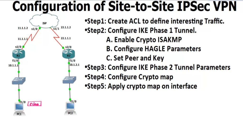
					R1
------
access-list 100 permit ip 10.1.1.0 0.0.0.255 10.1.2.0 0.0.0.255

crypto isakmp enable <Phase 1
.............................
crypto isakmp policy 1
encr 3des
hash md5
authentication pre-share
group 2
lifetime 8640
exit

crypto isakmp key 0 HQoffice address 22.1.1.1 <-R2 Public IP

crypto ipsec transform-set TS esp-3des esp-md5-hmac <IPSEC Tunnel Create
crypto map CMAP 10 ipsec-isakmp
set peer 12.1.1.1
set transform-set TS
match address 100


interface s2/0 <-Enable IPsec Router Interfaces
crypto map CMAP

ping 12.1.1.10 repeat 10000

IPsec Checking Commnd
---------------------
show crypto isakmp policy <-Checking Policy
show crypto isakmp key <-Checking key
show crypto ipsec transform-set
show crypto map
show crypto isakmp sa <-Checking Phase 1 Status
show crypto ipsec sa <-Checking Phase 2


R2
----------
access-list 100 permit ip 10.1.2.0 0.0.0.255 10.1.1.0 0.0.0.255

crypto isakmp enable
crypto isakmp policy 1
encr 3des
hash md5
authentication pre-share
group 2
lifetime 8640
exit

crypto isakmp key 0 HQoffice address 11.1.1.1 <-R1 Public IP

crypto ipsec transform-set TS esp-3des esp-md5-hmac
crypto map CMAP 10 ipsec-isakmp
set peer 12.1.1.1
set transform-set TS
match address 100

interface s2/0
crypto map CMAP

					hostname R1

router ospf 1

router-id 1.1.1.1


interface FastEthernet0/0

ip address 10.0.0.1 255.255.255.0

ip ospf 1 area 0

no shut


interface FastEthernet0/1

ip address 10.0.13.1 255.255.255.0

ip ospf 1 area 13

no shutdown


interface Serial1/0

ip address 10.0.12.1 255.255.255.0

ip ospf 1 area 12

no shut


interface Serial1/1

ip address 10.0.16.1 255.255.255.0

ip ospf 1 area 16

no shutdown
					hostname R2

router ospf 1

router-id 2.2.2.2

interface FastEthernet0/0

ip address 10.0.0.2 255.255.255.0

ip ospf 1 area 0

no shut


interface FastEthernet0/1

ip address 10.0.2.2 255.255.255.0

ip ospf 1 area 12

no shut


interface Serial1/0

ip address 10.0.12.2 255.255.255.0

ip ospf 1 area 12

no shut
					hostname R3

router ospf 1

router-id 3.3.3.3

interface FastEthernet0/0

ip address 10.0.0.3 255.255.255.0

ip ospf 1 area 0

no shut


interface FastEthernet0/1

ip address 10.0.13.3 255.255.255.0

ip ospf 1 area 13

no shut


interface loopback0

ip address 10.0.3.3 255.255.255.0

ip ospf 1 area 3
					hostname R4

router rip

version 2

network 10.0.0.0

no auto-summary

redistribute ospf 1 metric 1


router ospf 1

router-id 4.4.4.4

redistribute rip subnets

interface FastEthernet0/0

ip address 10.0.0.4 255.255.255.0

ip ospf 1 area 0

no shut


interface FastEthernet0/1

ip address 10.0.45.4 255.255.255.0

no shutdown
					hostname R5

interface FastEthernet0/1

ip address 10.0.45.5 255.255.255.0

no shut


interface loopback0

ip address 10.0.5.5 255.255.255.0

router rip

version 2

network 10.0.0.0

no auto-summary


hostname R6

router ospf 1

router-id 6.6.6.6

interface serial 1/1

ip address 10.0.16.6 255.255.255.0

ip ospf 1 area 16

no shutdown
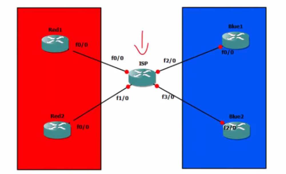
VRF LITE
int fa0/0
ip address 192.168.1.2 255.255.255.0
no shut
exit

int loopback 0
ip address 1.1.1.1 255.255.255.255

show ip route

router ospf 1
network 0.0.0.0 255.255.255.255 area 0 <1 Commnd OSPF Run All Interfaces>
					int fa0/0
ip address 192.168.2.2 255.255.255.0
no shut
exit


int loopback 0
ip address 2.2.2.2 255.255.255.255

show ip route

router ospf 1
network 0.0.0.0 255.255.255.255 area 0 <1 Commnd OSPF Run All Interfaces>
					int fa0/0
ip address 192.168.3.2 255.255.255.0
no shut
exit

int loopback 0
ip address 3.3.3.1 255.255.255.255

show ip route

router ospf 1
network 0.0.0.0 255.255.255.255 area 0 <1 Commnd OSPF Run All Interfaces>
					int fa0/0
ip address 192.168.4.2 255.255.255.0
no shut
exit

int loopback 0
ip address 4.4.4.1 255.255.255.255

show ip route

router ospf 1
network 0.0.0.0 255.255.255.255 area 0 <1 Commnd OSPF Run All Interfaces>
					ISP Router Config
ip vrf RED
exit
ip vrf BLUE
exit

show ip vrf

Red Customar Config
...................
interface FastEthernet 0/0
ip vrf forwarding RED
ip address 192.168.1.1 255.255.255.0
no shut
exit

router ospf 1 vrf RED
network 192.168.1.0 0.0.0.255 area 0
network 192.168.2.0 0.0.0.255 area 0

interface FastEthernet 1/0
ip vrf forwarding RED
ip address 192.168.2.1 255.255.255.0
no shut
exit

show ip vrf RED
show ip vrf

Blue Customar Config
....................

interface FastEthernet 2/0
ip vrf forwarding BLUE
ip address 192.168.3.1 255.255.255.0
no shut
exit

router ospf 1 vrf BLUE
network 192.168.3.0 0.0.0.255 area 0
network 192.168.4.0 0.0.0.255 area 0

interface FastEthernet 3/0
ip vrf forwarding BLUE
ip address 192.168.4.1 255.255.255.0
no shut
exit

show ip vrf RED
show ip vrf BLUE