
Inter-VLAN Routing
Inter-VLAN Routing
Understanding VLANs
Before diving into inter-VLAN routing, it’s crucial to understand VLANs and their role in networking.
What Are VLANs?
A VLAN (Virtual Local Area Network) is a logical subdivision of a physical network. VLANs group devices logically, regardless of their physical location, creating isolated domains for better traffic management and security. For example, HR, IT, and Finance departments in an organization can each have their own VLAN to segregate traffic.
Challenges of Isolated VLANs
While VLANs improve network performance and security, communication between them (inter-VLAN communication) is not inherently supported. Devices within one VLAN cannot directly communicate with devices in another, which can lead to data silos and operational inefficiencies. This is where inter-VLAN routing comes into play.
Inter-VLAN Routing is a method used in networking to allow communication between different VLANs (Virtual Local Area Networks). By default, devices in one VLAN cannot communicate with devices in another VLAN because each VLAN is a separate broadcast domain. Inter-VLAN routing solves this limitation by using a Layer 3 device (router or Layer 3 switch) to route traffic between VLANs.
1. Why Inter-VLAN Routing is Needed
In a network, VLANs are used to divide a large network into smaller, more secure, and manageable segments. However, sometimes devices in different VLANs need to communicate (for example, a PC in VLAN 10 accessing a server in VLAN 20). Since VLANs block direct communication, Inter-VLAN routing is required to enable this communication while maintaining segmentation and security.
2. How Inter-VLAN Routing Works
Inter-VLAN routing works by sending traffic from one VLAN to a Layer 3 device. This device routes the packet based on IP address and sends it to the destination VLAN. Each VLAN is assigned a unique IP subnet, and the router or Layer 3 switch has an interface (or virtual interface) in each VLAN, acting as the default gateway for devices in that VLAN.
3. Types of Inter-VLAN Routing
a) Legacy Inter-VLAN Routing (Router with Multiple Interfaces)
In this method, a router has separate physical interfaces connected to each VLAN. Each interface is configured with an IP address for that VLAN. This method is simple but not scalable because it requires many physical ports.
b) Router-on-a-Stick (ROAS)
This is the most common method. A single router interface is used with a trunk link connected to a switch. The router interface is divided into multiple subinterfaces, each configured for a specific VLAN using IEEE 802.1Q tagging. This method saves ports and is widely used in small to medium networks.
c) Layer 3 Switch (SVI – Switched Virtual Interface)
In modern networks, a Layer 3 switch performs Inter-VLAN routing using SVIs. Each VLAN has a virtual interface on the switch with an IP address. The switch routes traffic internally, making it faster than using a router. This is commonly used in enterprise networks.
4. Example of Inter-VLAN Routing
Suppose:
- VLAN 10 → 192.168.10.0/24
- VLAN 20 → 192.168.20.0/24
A PC in VLAN 10 (192.168.10.2) wants to communicate with a server in VLAN 20 (192.168.20.2). The PC sends the packet to its default gateway (e.g., 192.168.10.1). The Layer 3 device routes the packet to VLAN 20 and delivers it to the server.
5. Advantages of Inter-VLAN Routing
- Enables communication between different VLANs
- Improves network performance and management
- Enhances security by controlling traffic between VLANs
- Supports logical network segmentation
6. Disadvantages of Inter-VLAN Routing
- Requires Layer 3 devices (cost increases)
- Configuration complexity (especially in large networks)
- Router-on-a-stick can become a bottleneck if traffic is high
7. Real-World Use Case
In an office network:
- VLAN 10 → HR Department
- VLAN 20 → Finance Department
- VLAN 30 → IT Department
Inter-VLAN routing allows controlled communication between these departments, such as HR accessing a finance server, while still keeping departments logically separated.
Inter-VLAN (Virtual Local Area Network) refers to the communication between different VLANs within a network. VLANs are used to segment a network into smaller, isolated broadcast domains. By default, devices in different VLANs cannot communicate with each other directly because they are separated logically.
However, Inter-VLAN routing allows traffic to flow between these isolated VLANs. This can be achieved by using a router or a Layer 3 switch that supports routing between VLANs. Here’s how it typically works:
Router or Layer 3 Switch: A Layer 3 device, such as a router or a Layer 3 switch, is used to perform routing between the VLANs. The device will have interfaces configured for each VLAN (often called sub-interfaces) to handle the traffic.
Router-on-a-stick: This is a common technique where a single physical interface on a router is used for routing between multiple VLANs. The router uses sub-interfaces, each with its own IP address corresponding to the VLAN’s subnet.
Layer 3 Switch: If you have a Layer 3 switch, it can perform inter-VLAN routing without needing an external router. These switches operate at both Layer 2 and Layer 3 of the OSI model and are capable of routing traffic between VLANs directly.
In summary, Inter-VLAN routing enables different VLANs to communicate with each other, typically using a router or Layer 3 switch, and is a key part of managing network segmentation in larger networks.

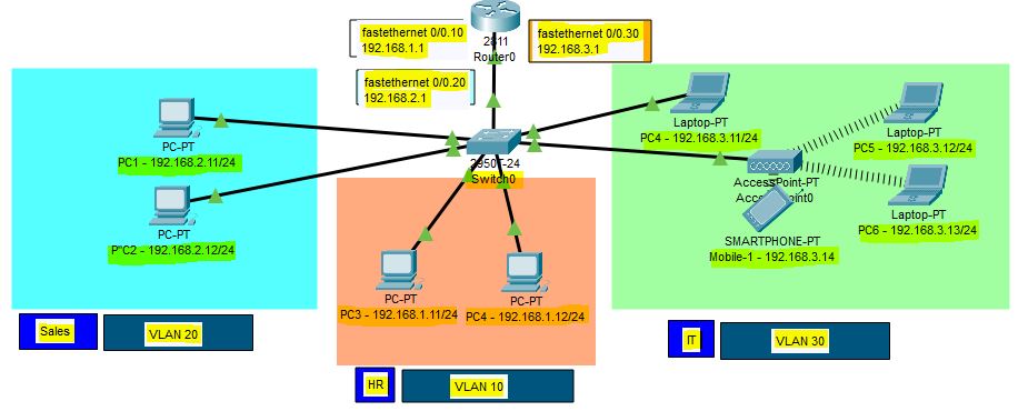


Router on a Stick

In this lesson, we are going to take a look at routing between VLANs. When we want communication between different VLANs, we’ll need a device that can do routing. We could use an external router, but it’s also possible to use a multilayer switch (aka layer three switches).
					SW1(config)#interface fa0/3
SW1(config-if)#switchport trunk encapsulation dot1q
SW1(config-if)#switchport mode trunk
SW1(config-if)#switchport trunk allowed vlan 10,20
This is how we configure SW1. Make interface fa0/3 a trunk port, and for security measures, I made sure that only VLAN 10 and 20 are allowed. Let’s create two sub-interfaces and assign the correct VLANs:
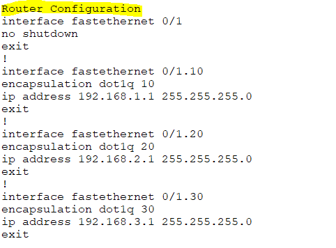
					R1(config)#interface fa0/0.10
R1(config-subif)#encapsulation dot1Q 10
R1(config-subif)#ip address 192.168.10.254 255.255.255.0
R1(config)#interface fa0/0.20
R1(config-subif)#encapsulation dot1Q 20
R1(config-subif)#ip address 192.168.20.254 255.255.255.0
Don’t forget to add an IP address for each VLAN. Here’s what the routing table looks like:
					R1#show ip route
Codes: C - connected, S - static, R - RIP, M - mobile, B - BGP
       D - EIGRP, EX - EIGRP external, O - OSPF, IA - OSPF inter area
       N1 - OSPF NSSA external type 1, N2 - OSPF NSSA external type 2
       E1 - OSPF external type 1, E2 - OSPF external type 2
       i - IS-IS, su - IS-IS summary, L1 - IS-IS level-1, L2 - IS-IS level-2
       ia - IS-IS inter area, * - candidate default, U - per-user static route
       o - ODR, P - periodic downloaded static route
Gateway of last resort is not set
C    192.168.10.0/24 is directly connected, FastEthernet0/0.10
C    192.168.20.0/24 is directly connected, FastEthernet0/0.20
SVI (Switch Virtual Interface)

What is SVI?
An SVI (Switched Virtual Interface) is a virtual interface on a Layer 3 switch used to provide Layer 3 (IP) functionality to a VLAN on a network. It allows the switch to perform routing functions for that VLAN. Essentially, an SVI acts as the default gateway for all devices in the VLAN it is associated with.
Here are key points about an SVI:
Layer 3 Interface: Although VLANs are typically associated with Layer 2 (data link layer) functionality, the SVI allows a Layer 3 switch to route traffic between VLANs. This provides IP routing capabilities for each VLAN.
VLAN and IP Address: Each SVI is associated with a specific VLAN and typically has an IP address configured on it. Devices within that VLAN will use the SVI’s IP address as their default gateway, allowing them to communicate with devices outside of their VLAN.
No Physical Interface: Unlike traditional interfaces on routers or Layer 2 switches, an SVI does not correspond to a physical interface. It’s purely virtual and exists in software on the switch.
Routing Between VLANs: When you configure an SVI, it enables the Layer 3 switch to perform routing between multiple VLANs. This is known as inter-VLAN routing.
For example, if you have two VLANs (VLAN 10 and VLAN 20), you could configure an SVI for each VLAN on a Layer 3 switch:
- VLAN 10’s SVI would have an IP address like
192.168.10.1. - VLAN 20’s SVI would have an IP address like
192.168.20.1.
These IP addresses would serve as the default gateways for devices in VLAN 10 and VLAN 20. Traffic between VLANs would be routed by the switch via the SVIs.
Key Benefits of SVIs:
Efficient Routing: SVIs provide a quick and efficient method of routing traffic between VLANs without needing an external router.
Simplified Configuration: On Layer 3 switches, SVIs make it easy to implement inter-VLAN routing with minimal hardware.
Scalability: You can have multiple SVIs on a single Layer 3 switch, making it scalable for larger networks with many VLANs.
In summary, an SVI allows a Layer 3 switch to route traffic between VLANs, acting as a gateway for each VLAN while remaining a virtual (non-physical) interface.
InterVLAN Routing Using Layer 3 Switch

Multilayer Switches
A switch is a device that typically operates at layer 2 of the OSI model. It inspects frames and switches them between interfaces based on MAC addresses found in the Ethernet header. This type of device is referred to as just a switch or a Layer 2 switch. It does not look deeper than the Ethernet header and does not make any decisions based on information in the IP header. Routers, on the other hand, strip the Ethernet header of frames and look at the packet in the frame’s payload. They make routing decisions based on the IP addresses found in the Layer 3 header and place a new Ethernet header before switching the frame out to another interface.
A multilayer switch can perform both functions explained above at incredibly fast speeds. It can switch frames as a regular switch and can perform IP routing as a router. Therefore, it can perform functions at layer 2 and layer 3 of the OSI model. That is why such a device is called a Multilayer Switch or a Layer 3 switch.
Why do we need Layer 3 switches?
Back in the old days, when the networks started to grow rapidly, people realized that it was unscalable to perform InterVlan routing at the router layer of the network. For example, when the network scales to the point where there are multiple layers of switches: access, distribution, and core, if you want to perform InterVLAN routing using routers, you must extend the VLANs up to the routers. This creates some serious problems:
- Unscalable—Look where the routers are in the three-tier design. If these devices are to perform inter-VLAN routing, we must extend the VLANs all the way to the top of the network topology. However, large Layer 2 networks with many switches and VLANs are hard to manage. Additionally, the Spanning Tree Protocol (STP) blocks all redundant ports and slows down the convergence.
- Large fault domain—If there’s a loop or broadcast storm in the Layer 2 network, it can bring down the whole network. There’s no fault isolation between sections of the network.
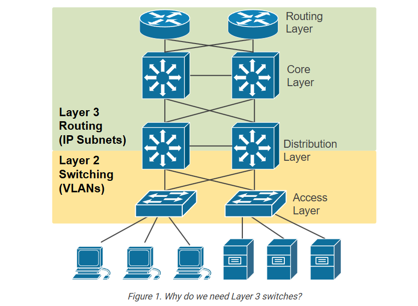
The industry realized that switches needed to be able to perform switching and routing at the same time. With InterVLAN routing done by switches at the distribution layer, the network could be separated into access, distribution, and core layers. This improved fault isolation and allowed the network to scale.
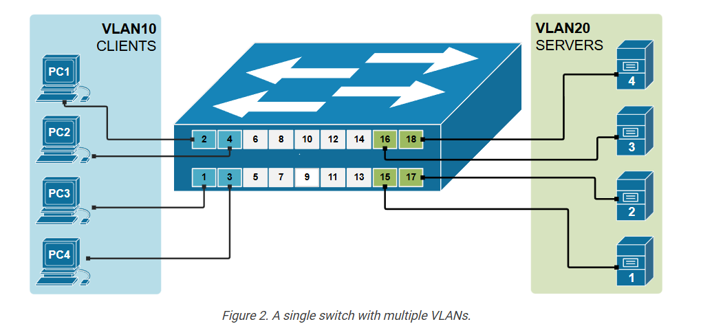
On the other side of the spectrum, there was also a problem: very small networks with only one switch with multiple VLANs needed a router to do the InterVLAN routing. For example, if we look closer at the topology shown in the diagram below, we have four clients in Vlan 10 and four servers in Vlan 20. Clients and Servers are in separate broadcast domains and different subnets. Therefore, for clients in VLAN 10 to be able to communicate with the Servers in VLAN20, IP
However, routers are usually much more expensive than switches. In many cases, a router can cost 5 to 10 times more than a similar switch. This is because routers are built for advanced features, like wide-area networks (WAN) and complex routing protocols. They also have fewer interfaces than switches.
The industry realized that it doesn’t make sense to use an expensive router in the LAN simply to perform InterVLAN routing. It is not cost-efficient for small and medium businesses.
Those two inefficiencies of using routers for InterVLAN routing have led to the introduction of switches with embedded routing functionality called Layer 3 switches.
What is a Layer 3 switch?
A Layer 3 switch has an IP routing process that can route packets based on the IP address information in the Layer 3 header. This means it checks the destination IP address in each packet and decides where to send it, just like a router.
It uses a routing table to find the best path to the destination network. The routing is done in hardware (using ASICs), so it’s much faster than traditional routers that use software-based routing. So, a Layer 3 switch can forward packets between different IP subnets using this built-in routing function.
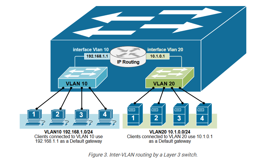
As you know from the previous two examples of Inter-VLAN routing, the router has a routing interface in each VLAN. This routing interface has an IP address from the respective subnet, and the nodes in the vlan use this IP as a Default Gateway. But in the case of a Layer 3 switch, we do not have a router or any routing interfaces. That is why Layer 3 switches use the concept of an SVI interface that connects a Vlan to the routing process, as shown in the diagram above. SVI stands for Switched Virtual Interface. For example, interface Vlan 10 connects to VLAN 10, and interface VLAN 20 connects to VLAN 20.
An SVI interface is created using the following command in global configuration mode:
					L3Switch(config)# interface Vlan10
%LINK-5-CHANGED: Interface Vlan10, changed state to up
%LINEPROTO-5-UPDOWN: Line protocol on Interface Vlan10,
changed state to up
Once the interface is defined, we configure the IP parameters under the interface onfiguration mode.
					L3Switch(config-if)# description VLAN10
L3Switch(config-if)# ip address 192.168.1.1 255.255.255.0
L3Switch(config-if)# no shutdown
An SVI interface is configured and works the same as a physical router interface, but it is virtual. The main difference is that an SVI doesn’t use a physical port. Instead, it uses the switch’s internal hardware to route traffic between VLANs. It behaves just like a router interface, but it’s created in software and linked to a VLAN, as shown in the diagram below.
Notice that instead of a physical external router, the inter-Vlan routing functionality is performed by the switch itself.
Configuration Example
Now, let’s demonstrate how we configure a multiplayer switch to route between two virtual LANs.
Physical diagram
In this example, we will learn to configure a multilayer switch (also called Layer 3 switch) to perform inter-VLAN routing, which was previously done using an actual router. Multilayer switches can forward frames based on MAC address information and can also forward IP packets based on IP destination. That is why they are also referred to as Layer 3 switches.
The diagram below shows the physical topology that we are going to use for this demonstration. Note that there is no router present because the switch itself will perform the Inter-VLAN routing.
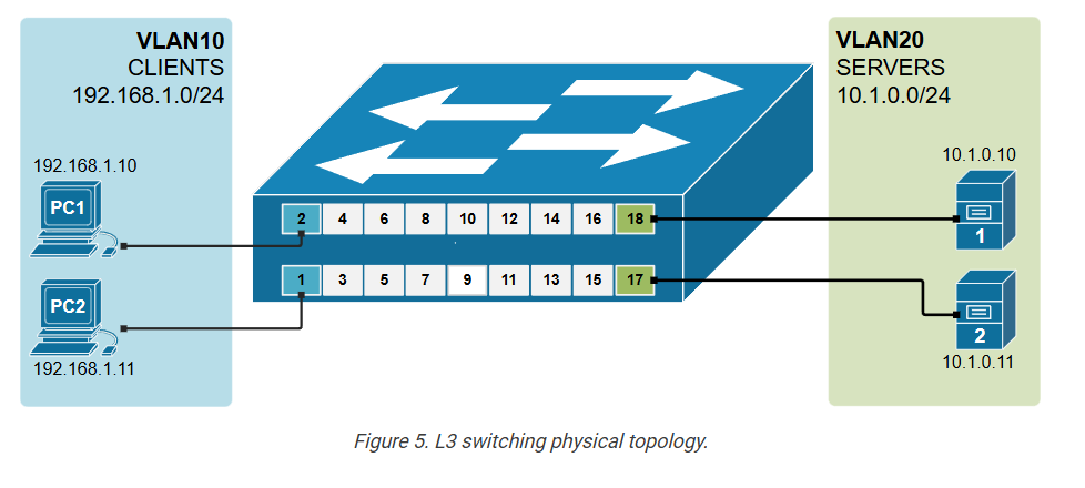
The topology is a greenfield deployment. All devices are with their factory-default settings.
Configuring the switch
Let’s first see all available interfaces on the switch. Note that the ports where we have connected devices are up/up, and all other switch ports are down/down. Also pay attention that by default there is one SVI interface already configured on the switch – the default Vlan1’s SVI.
					L3Switch# show ip interface brief
Interface              IP-Address      OK? Method Status                Protocol
FastEthernet0/1        unassigned      YES unset  up                    up
FastEthernet0/2        unassigned      YES unset  up                    up
FastEthernet0/3        unassigned      YES unset  up                    up
FastEthernet0/4        unassigned      YES unset  up                    up
FastEthernet0/5        unassigned      YES unset  down                  down
FastEthernet0/6        unassigned      YES unset  down                  down
FastEthernet0/7        unassigned      YES unset  down                  down
FastEthernet0/8        unassigned      YES unset  down                  down
FastEthernet0/9        unassigned      YES unset  down                  down
FastEthernet0/10       unassigned      YES unset  down                  down
FastEthernet0/11       unassigned      YES unset  down                  down
FastEthernet0/12       unassigned      YES unset  down                  down
FastEthernet0/13       unassigned      YES unset  down                  down
FastEthernet0/14       unassigned      YES unset  down                  down
FastEthernet0/15       unassigned      YES unset  up                    up
FastEthernet0/16       unassigned      YES unset  up                    up
FastEthernet0/17       unassigned      YES unset  up                    up
FastEthernet0/18       unassigned      YES unset  up                    up
GigabitEthernet0/1     unassigned      YES unset  down                  down
GigabitEthernet0/2     unassigned      YES unset  down                  down
Vlan1                  unassigned      YES unset  administratively down down
Let’s create two VLANs – VLAN10 (Clients) and VLAN20 (Servers) and assign the interfaces to the respective VLANs.
					L3Switch(config)# vlan 10
L3Switch(config-vlan)# name CLIENTS
L3Switch(config-vlan)# exit
!
L3Switch(config)# vlan 20
L3Switch(config-vlan)# name SERVERS
L3Switch(config-vlan)# exit
Now, let’s assign the ports where the end devices connect to the correct VLANs, according to the physical diagram.
					L3Switch# conf t
Enter configuration commands, one per line.  End with CNTL/Z.
L3Switch(config)# interface range fastEthernet 0/1 - 2
L3Switch(config-if-range)# switchport access vlan 10
L3Switch(config-if-range)# exit
L3Switch(config)# interface range fastEthernet 0/17 - 18
L3Switch(config-if-range)# switchport access vlan 20
L3Switch(config-if-range)# end
Let’s verify that the VLANs are configured and the ports are correctly assigned using the following command.
					L3Switch# show vlan brief

VLAN Name                             Status    Ports
---- -------------------------------- --------- -------------------------------
1    default                          active    Fa0/5, Fa0/6, Fa0/3, Fa0/4, Fa0/7,
                                                Fa0/8, Fa0/9, Fa0/10, Fa0/11, Fa0/12
                                                Fa0/13, Fa0/14, Fa0/15, Fa0/16,
                                                Gig0/1, Gig0/2
10   CLIENTS                          active    Fa0/1, Fa0/2
20   SERVERS                          active    Fa0/17, Fa0/18
1002 fddi-default                     active
1003 token-ring-default               active
1004 fddinet-default                  active
1005 trnet-default                    active
Configuring the switch’s IP routing functionality
The second step in the process is to enable the switch’s IP routing functionality using the following command in global configuration mode.
L3Swtich(config)# ip routing
The next step is to configure the SVi interfaces for each VLAN and assign them an IP ddress.
					L3Swtich# configure terminal
Enter configuration commands, one per line.  End with CNTL/Z.
L3Swtich(config)# interface Vlan10
%LINK-5-CHANGED: Interface Vlan10, changed state to up
%LINEPROTO-5-UPDOWN: Line protocol on Interface Vlan10, changed state to up
L3Swtich(config-if)# description CLIENTS
L3Swtich(config-if)# ip address 192.168.1.1 255.255.255.0
L3Swtich(config-if)# exit
L3Swtich(config)# interface Vlan20
%LINK-5-CHANGED: Interface Vlan20, changed state to up
%LINEPROTO-5-UPDOWN: Line protocol on Interface Vlan20, changed state to up
L3Swtich(config-if)# description SERVERS
L3Swtich(config-if)# ip address 10.1.0.1 255.255.255.0
L3Swtich(config-if)# end
Now, the switch has routing interfaces in both VLANs and both subnets in its routing table, which is shown as Connected.
					L3Switch# show ip route

Codes: C - connected, S - static, I - IGRP, R - RIP, M - mobile, B - BGP
       D - EIGRP, EX - EIGRP external, O - OSPF, IA - OSPF inter area
       N1 - OSPF NSSA external type 1, N2 - OSPF NSSA external type 2
       E1 - OSPF external type 1, E2 - OSPF external type 2, E - EGP
       i - IS-IS, L1 - IS-IS level-1, L2 - IS-IS level-2, ia - IS-IS inter area
       * - candidate default, U - per-user static route, o - ODR
       P - periodic downloaded static route
Gateway of last resort is not set
     10.0.0.0/24 is subnetted, 1 subnets
C    10.1.0.0 is directly connected, Vlan20
C    192.168.1.0/24 is directly connected, Vlan10
Configuring End Hosts
The last step to enable inter-VLAN routing is to configure each end host with the correct IP address, subnet mask, and default gateway.
- The IP address must match the VLAN’s subnet.
- The default gateway must be the IP address of the SVI for that VLAN.
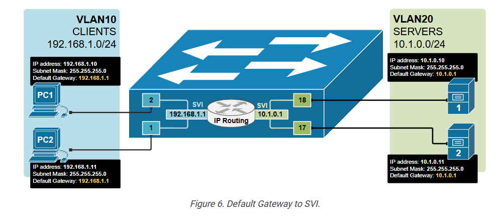
This allows the host to send traffic to devices in other VLANs through the switch’s Layer 3 routing process. Without the correct gateway, devices can only talk to others on the same VLAN.
Key Takeaways
- Layer 3 switches can perform both switching (Layer 2) and routing (Layer 3) functions.
- They use hardware-based (ASIC) routing, which is much faster than traditional routers.
- They are commonly used in enterprise LANs, especially in distribution and core layers.
- Layer 3 switches made the three-tier network design possible by allowing fast inter-VLAN routing.
- SVI (Switched Virtual Interface) is a virtual Layer 3 interface for a VLAN.
- An SVI acts like a router interface, providing an IP gateway for devices in that VLAN.
- To use SVIs for routing between VLANs, you must enable the ip routing command.
- SVIs make routing inside the switch faster and more efficient without needing external