Switch Stacking Technology
What is Switch Stacking
- Switch stacking is a networking technology that allows multiple physical network switches to be interconnected and operate as a single logical switch. From the perspective of network administrators and connected devices, a stack of switches behaves like one large switch with a single management IP address and one unified configuration. This simplifies network management because all stacked switches can be controlled, monitored, and configured from one interface instead of managing each switch separately.
- In switch stacking, the switches are connected using special stacking cables or dedicated stack ports that provide very high-speed communication between the devices. One switch in the stack is elected as the master (or primary) switch, which is responsible for managing the entire stack, handling configuration files, and controlling data forwarding decisions. The remaining switches act as member switches and follow the master’s instructions.
- A key advantage of switch stacking is high availability and redundancy. If the master switch fails due to hardware or power issues, another switch in the stack automatically takes over as the new master without disrupting network operations for long. This failover mechanism ensures continuous network service and reduces downtime, which is especially important in business and enterprise environments.
- Switch stacking also improves scalability and performance. When an organization needs more network ports, additional switches can simply be added to the existing stack instead of deploying and managing a completely new device. Because stacking links usually have much higher bandwidth than normal Ethernet links, traffic between switches in the stack flows quickly and efficiently, reducing congestion and improving overall network performance.
- Overall, switch stacking provides a cost-effective and efficient way to build a larger, more reliable network using multiple smaller switches. It combines simplified management, better fault tolerance, and easy expansion, making it ideal for office networks, campus environments, and enterprise access-layer deployments where reliability and growth are important.
Switch Stacking How Works
What is Switch Stacking?
Switch stacking is a technology that allows multiple network switches to work together as one logical switch. Instead of managing each switch separately, all stacked switches operate as a single unit. They share one control plane, one configuration, and one management IP address. This makes the network easier to manage and increases performance and reliability.
How Switch Stacking Works?
In switch stacking, several switches are connected using special stacking cables or stacking ports. These ports create a high-speed connection between the switches. After connection, the switches exchange information and elect one switch as the master switch (or stack master). The remaining switches become member switches.
The master switch controls the entire stack. It manages routing tables, VLAN information, security settings, and forwarding decisions for all switches in the stack. Member switches forward traffic based on the instructions from the master.
Communication Between Stacked Switches?
All switches in the stack communicate through a dedicated stacking bandwidth. This bandwidth is usually much faster than normal Ethernet links. When a device connected to one switch wants to communicate with a device connected to another switch in the stack, the data travels through the stacking links internally. To connected devices, the entire stack appears as a single switch.
For example, if PC1 is connected to Switch 1 and PC2 is connected to Switch 3, the stack transfers data internally without needing external uplinks between switches.
Master Switch Election Process?
When the stack powers on, switches participate in an election process to select the master switch. The election may depend on factors such as:
- Switch priority value
- Hardware capability
- Existing configuration
- MAC address
The switch with the highest priority usually becomes the master. If the master switch fails, another member switch automatically takes over, ensuring network continuity.
Advantages of Switch Stacking?
1. Easy Management
Administrators can configure and monitor all switches using a single interface or IP address. This reduces configuration complexity.
2. High Availability
If one switch fails, the other switches in the stack continue working. Network downtime is minimized.
3. Scalability
More switches can be added to the stack when the network grows, without redesigning the entire network.
4. Better Performance
Stacking provides high-speed communication between switches and reduces bottlenecks.
5. Simplified Cabling
Instead of many uplink cables between switches, stacking cables create direct internal communication links.
Types of Switch Stacking?
Physical Stacking
Switches are connected using dedicated stacking ports and cables. This provides high speed and low latency.
Virtual Stacking
Some switches use normal Ethernet ports and software technology to create a virtual stack. This is slower than physical stacking but useful in some environments.
Real Example of Switch Stacking?
- Switch stacking is a networking technology in which multiple physical switches are connected together so that they work as one logical switch. In real office networks, companies often use stacking to increase the number of ports while keeping management simple. Instead of configuring each switch separately, the administrator manages the entire stack as a single device.
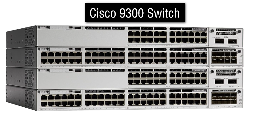
- For example, suppose a company has a three-floor building. One switch is installed on each floor using switches such as Cisco Catalyst 9300. These switches are connected with special stacking cables through dedicated stack ports. After the connection is completed, the switches automatically form one stack.
- When the stack starts, one switch becomes the master switch. The master controls the entire stack and stores the main configuration. The other switches become member switches and follow the instructions of the master. Users connected to different switches can communicate normally because the switches exchange data internally through the stacking links.
- Assume an employee on the first floor sends a file to another employee on the third floor. Even though both computers are connected to different physical switches, the stack forwards the traffic internally at high speed. To users and devices, the whole stack behaves like one large switch.
- Switch stacking also simplifies management. Without stacking, the administrator must configure VLANs, security settings, and monitoring separately on every switch. With stacking, only one management IP address is used. A configuration applied on the master switch automatically affects all member switches in the stack.
- Another important advantage is redundancy. If the master switch fails because of power loss or hardware problems, another switch in the stack automatically becomes the new master. This reduces downtime and keeps the network running with minimal interruption.
- Large organizations such as colleges, hospitals, banks, and corporate offices commonly use switch stacking. It helps them expand the network easily, improve performance, reduce cable complexity, and simplify administration. Because of these benefits, switch stacking is widely used in modern enterprise networks.
OR
Real Example of Switch Stacking?
Suppose a company has a three-floor office building. Each floor has many computers, printers, IP phones, and Wi-Fi access points. The network administrator installs three switches:
- Floor 1 → Cisco Catalyst 9300
- Floor 2 → Cisco Catalyst 9300
- Floor 3 → Cisco Catalyst 9300
These switches are connected using special stacking cables. After stacking, all three switches work like one single large switch.
How It Works in Real Life
Each employee connects their PC to the nearest switch on their floor. Even though users are connected to different physical switches, the stack handles everything centrally.
For example:
- Employee A on Floor 1 sends a file to Employee B on Floor 3.
- The data travels through the stack connection internally.
- Users do not notice that different switches are involved.
The communication is fast because stacking links provide high-speed internal bandwidth.
Single Management Example
Without stacking:
- Administrator must log in to 3 separate switches.
- VLANs and security settings must be configured three times.
- Software updates must be done separately.
With stacking:
- Only one management IP address is used.
- Administrator configures VLAN once, and it applies to all switches.
- Monitoring and troubleshooting become easier.
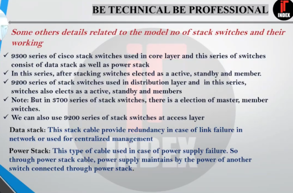
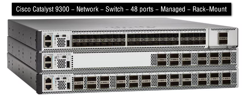
C9300-24T-A - Catalyst 9300 24-Port Data Only Price Rs 2,50,000
The Cisco® Catalyst® 9300 Series Switches are Cisco’s lead stackable enterprise switching platform built for security, IoT, mobility, and cloud. C9300-24T-A is 24port data only, Network Advantage Switch of 9300 series. Catalyst 9300 Series are the next generation of the industry’s most widely deployed switching platform. At 480 Gbps, they are the industry’s highest-density stacking bandwidth solution with the most exible uplink architecture. The Catalyst 9300 Series is the rst optimized platform for high-density 802.11ac Wave2. It sets new maximums for network scale. These switches are also ready for the future, with an x86 CPU architecture and more memory, enabling them to host containers and run third-party applications and scripts natively within the switch.
Example command in a Cisco stack:
					show switch

Switch#   Role      Priority   State
1         Master    15         Ready
2         Member    10         Ready
3         Member    10         Ready
Switch 1 controls the stack as the master.
Switches 2 and 3 are member switches.
Failure Example?
Imagine Switch 1 (master) suddenly fails because of power loss.
What happens?
- Another switch automatically becomes the new master.
- Users connected to Switch 2 and Switch 3 continue working.
- Network downtime is very small.
This is why switch stacking is important for reliability.
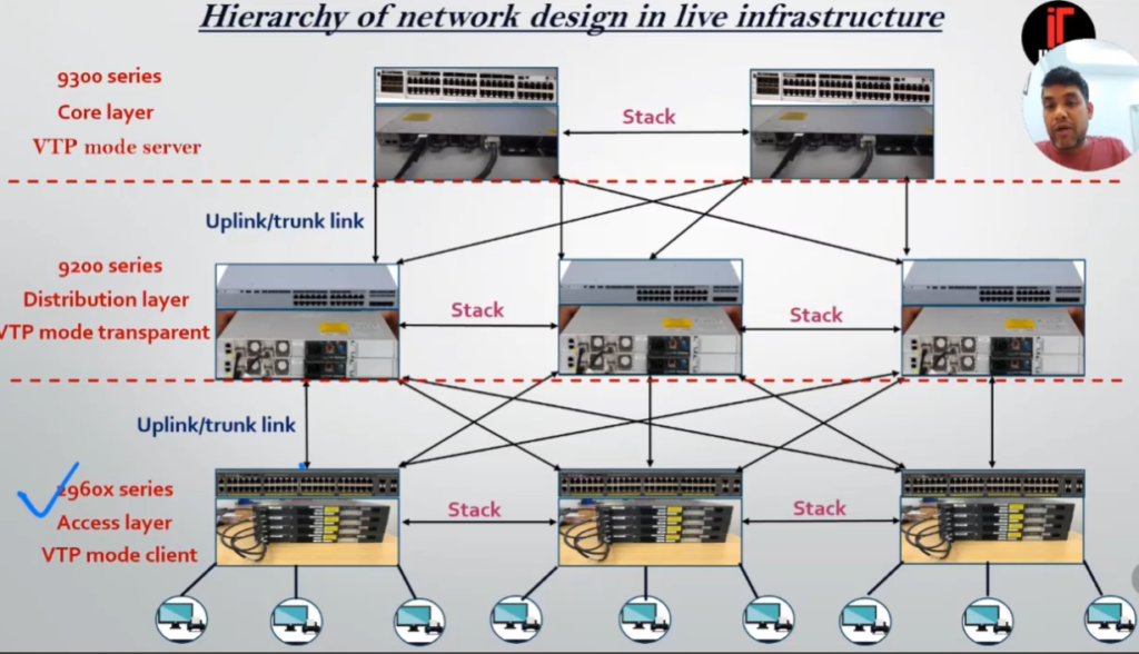
Real Network Design Example?
In many colleges, companies, and hospitals:
- Access layer switches on each floor are stacked together.
- The stack connects upward to a core switch.
- The network behaves more efficiently and is easier to maintain.
Cisco provides many switch models that support stacking technology. These switches are mainly used in enterprise networks, offices, colleges, hospitals, and data centers. Different Cisco series support different stacking technologies such as StackWise, StackWise-80, StackWise-160, and Virtual StackWise.
Common Cisco Stack Switch Models
| Series | Example Models | Stacking Technology | Usage |
|---|---|---|---|
| Catalyst 9200 Series | Cisco Catalyst 9200 Layer 3 Switch | StackWise-80 / StackWise-160 | Small and medium enterprise |
| Catalyst 9300 Series | Cisco Catalyst 9300 | StackWise-480 / StackWise-1T | Enterprise access layer |
| Catalyst 3850 Series | Cisco Catalyst 3850 Layer 3 Switch | StackWise-480 | Campus networks |
| Catalyst 2960-X Series | Cisco WS-C2960X-48TS-L | FlexStack-Plus | Small office and branch |
| Nexus 9300 Series | Cisco N9K-93128TX Nexus 9300 Series 96×10G Managed Ethernet Switch |
Cisco Catalyst 9200 Series:
The Cisco Catalyst 9200 Layer 3 Switch is one of the most commonly used stackable switches in modern enterprise networks. It supports StackWise technology and allows multiple switches to operate as one logical switch. These switches are widely used in schools, offices, and branch networks because they provide security, high performance, and easy management. Cisco states that some 9200 models support stack bandwidth up to 160 Gbps.
Popular models include:
- C9200-24T
- C9200-48T
- C9200-24P
- C9200-48P
- C9200L-24T-4G
- C9200L-48P-4X
Switch Stacking Benefits
- Switch stacking provides several important benefits that make it a popular choice in enterprise and campus networks. One of the main advantages is simplified management. When multiple switches are stacked, they operate as a single logical switch with one IP address and one configuration file. This allows network administrators to configure, monitor, and troubleshoot the entire stack from a single interface instead of managing each switch separately, saving time and reducing complexity.
- Another major benefit of switch stacking is high availability and redundancy. If one switch in the stack fails due to hardware or power issues, another switch automatically takes over as the master. Network connectivity for users and devices continues with minimal interruption. This built-in failover mechanism helps ensure continuous service and reduces network downtime in business environments.
- Switch stacking also supports easy scalability and expansion. As network requirements grow, additional switches can be added to the stack without redesigning the network. This makes it simple to increase the number of ports while keeping the same configuration and management structure. Organizations can expand their network gradually instead of investing in a large chassis switch from the beginning.
- Performance is another key benefit. The dedicated stacking links provide high-speed communication between switches, which is much faster and more efficient than using regular Ethernet uplinks between separate switches. This improves traffic flow inside the network and helps reduce congestion, especially in environments with heavy data usage.
- Overall, switch stacking offers a reliable and cost-effective solution by combining multiple switches into one logical unit. It improves manageability, provides redundancy, enhances performance, and allows flexible growth, making it ideal for office networks, campuses, and enterprise access-layer deployments.
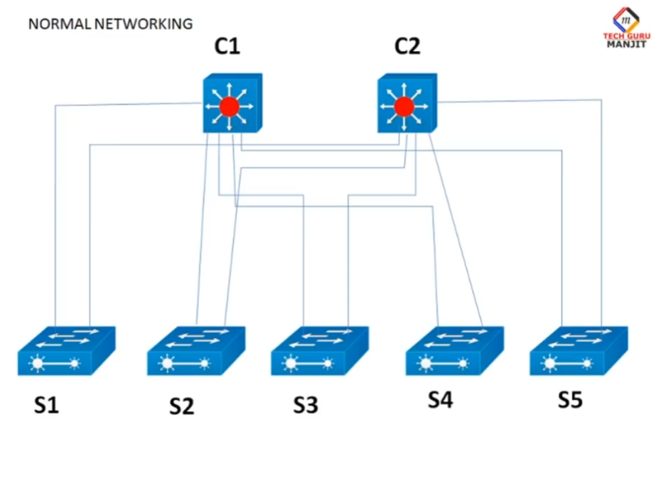
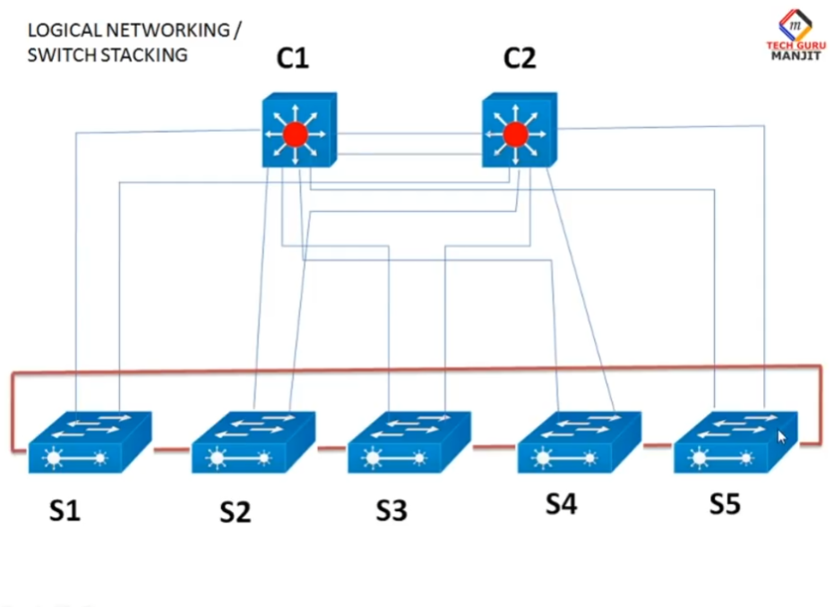
Network Example of Switch Stacking
Here is a Company Network example of Switch Stacking
- In a medium-sized company office, there are about 150 employees who use computers, IP phones, printers, and Wi-Fi access points. The IT department installs three 48-port managed switches in the server room. Instead of configuring and managing each switch separately, the switches are connected together using stacking cables and configured as a single switch stack. Now, all three physical switches behave like one logical switch with one management IP address and one configuration file.
- For example, all employee PCs are connected across the three stacked switches, but VLANs for different departments such as HR, Finance, and IT are configured only once on the master switch and automatically applied to all member switches. If one switch in the stack fails due to power or hardware problems, the remaining switches continue to forward traffic without major interruption, and one of them automatically becomes the new master. Employees can continue working with little or no downtime.
- This setup also makes future expansion easy for the company. When the business grows and more users are added, the IT team can simply add another switch to the existing stack instead of building a new network segment. The new switch immediately becomes part of the same logical system and follows the same security policies, VLANs, and management rules. In this way, switch stacking helps the company maintain a simple, reliable, and scalable network infrastructure with minimum management effort and maximum availability.
4 Switch Stacking
- In a network where four switches are connected using switch stacking, STP (Spanning Tree Protocol does NOT block ports between the stacked switches) because the entire stack is treated as one single logical switch (one bridge ID). Since STP works based on bridge IDs, it does not see the individual stacked switches as separate devices. Therefore, there is no STP loop inside the stack, and all stack links remain active and forwarding traffic normally.
- Regarding the control plane traffic, stacked switches continuously exchange control-plane information such as configuration data, MAC tables, routing information, and STP state through the dedicated stacking links. One switch acts as the master (or active switch) and manages the control plane for the whole stack. The other switches act as members and synchronize their control-plane information with the master. This internal control-plane traffic is handled automatically and does not interfere with normal user data traffic.
- However, if those four switches are not stacked and are connected in a loop topology using normal Ethernet links, then STP will detect a loop and block one or more ports to prevent broadcast storms. In that case, STP does affect traffic flow by placing some ports in the blocking state. But in a true switch stack, STP treats the stack as one device, so no internal ports are blocked and performance is much better.
- In summary, with switch stacking, STP does not block ports between the stacked switches, and control-plane traffic is managed internally by the master switch over high-speed stack links. This is one of the main advantages of switch stacking over connecting multiple independent switches with STP.
Types of Switch Stacking
There are different types of switch stacking, based on how switches are connected and how they operate as one logical unit. These types depend on the technology and vendor implementation. The main types of switch stacking are explained below.
1. Physical (True) Switch Stacking
In physical stacking, switches are connected using dedicated stacking ports and stacking cables. All switches operate as one logical switch with one control plane and one management IP address. One switch becomes the master and others become members. This type provides high bandwidth and fast failover. It is the most common and reliable form of switch stacking used in enterprise networks.
Example technologies:
- Cisco StackWise
- HPE IRF
- Juniper Virtual Chassis
2. Virtual Stacking (Logical Stacking)
In virtual stacking, switches are connected using normal Ethernet or fiber ports instead of special stacking cables. They still appear as one logical switch for management, but performance is usually lower than physical stacking. Control plane is shared logically, and the switches synchronize configurations over network links.
This is useful when stacking ports are not available or when switches are in different racks.
3. Ring Topology Stacking
In ring stacking, switches are connected in a closed loop (ring) using stacking cables. This provides redundancy, because if one stacking link fails, traffic can still flow in the opposite direction around the ring. It is the most fault-tolerant stacking topology and commonly used in production networks.
4. Chain (Linear) Topology Stacking
In chain stacking, switches are connected one after another in a straight line. It is simple to implement but has less redundancy. If a middle switch or stacking cable fails, the stack can split into two parts.
5. Vendor-Specific Stacking Types
Different vendors use their own stacking technologies:
- Cisco – StackWise / StackWise Virtual
- HPE – Intelligent Resilient Framework (IRF)
- Juniper – Virtual Chassis
- Dell – Dell EMC Stacking
Each vendor has limits on how many switches can be stacked and which models are compatible.
Switch Stacking Master And Slave
- In switch stacking, multiple physical switches are combined to work as one logical switch. Among these switches, one is elected as the Master (or Active) switch, and the others become Slave (or Member) switches. This master–slave architecture allows the entire stack to be managed and controlled as a single device, which simplifies network operation and improves reliability.
- The Master switch is the brain of the switch stack. It controls the control plane, which means it is responsible for running network protocols such as STP, VLAN management, routing (if Layer-3 is enabled), and link aggregation. The master also stores and applies the configuration for the whole stack and provides the single management IP address used by administrators. All decisions about how traffic should be forwarded inside and outside the stack are calculated by the master switch.
- The Slave (Member) switches mainly handle the data plane, which is the actual forwarding of user traffic such as PC data, server traffic, and internet packets. They follow the instructions and configuration received from the master switch. Slave switches synchronize their MAC address tables, VLAN information, and port status with the master through the high-speed stacking links. From the administrator’s point of view, these slave switches do not act independently; they behave as line cards of one big switch.
- A very important feature of master and slave operation is failover and redundancy. If the master switch fails due to power or hardware problems, one of the slave switches is automatically elected as the new master. This process usually happens quickly, and the network continues to function with minimal disruption. This ensures high availability and prevents long downtime in company or enterprise networks.
- In summary, the master switch manages and controls the entire switch stack, while the slave switches forward traffic and follow the master’s configuration. Together, they act as one logical switch with centralized control, better performance, and built-in redundancy, making switch stacking a reliable and scalable solution for modern networks.
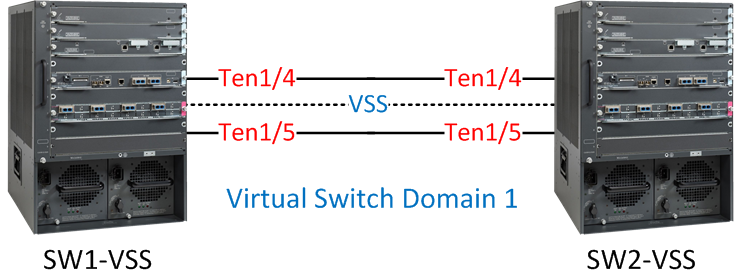
What is VSS
What is VSS?
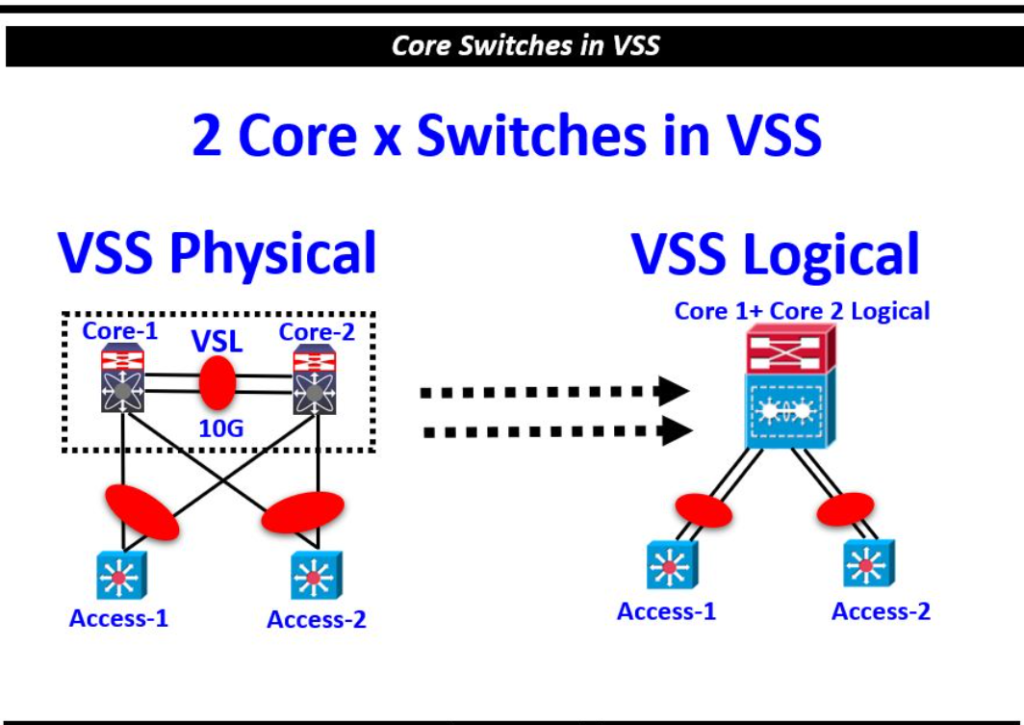
VSS stands for Virtual Switching System. It is a Cisco technology that combines two physical switches into one logical switch. With VSS, both switches work together as a single device, sharing one control plane, one configuration file, and one management IP address.
VSS is mainly used in core and distribution layer networks to improve redundancy, scalability, and high availability. It is commonly supported on high-end Cisco switches such as the Cisco Catalyst 6500 and Cisco Catalyst 6800 series.
How VSS Works?
In a VSS setup, two physical switches are connected using a special high-speed link called the Virtual Switch Link (VSL). The VSL carries control traffic, synchronization information, and user data between the two switches.
After VSS is configured:
- The two switches appear as one logical switch
- One switch becomes the active switch
- The other becomes the standby switch
- Both share the same configuration and routing information
To connected devices, the two switches behave like a single switch.
Real Example of VSS?
Suppose a company has two core switches in a data center:
- Core Switch 1 → Cisco Catalyst 6509
- Core Switch 2 → Cisco Catalyst 6509
Normally, these switches would operate separately. With VSS enabled, they become one logical core switch.
Access switches connect to both physical chassis at the same time. If one chassis fails, traffic automatically continues through the other chassis without major interruption.
Active and Standby Roles
Inside the VSS domain:
- The active switch controls routing, forwarding, and management tasks.
- The standby switch stays synchronized and ready to take over if the active switch fails.
This provides fast failover and improves network reliability.
Advantages of VSS
Simplified Management
The administrator manages both switches using one configuration and one IP address. This reduces operational complexity.
High Availability
If one switch fails, the second switch continues forwarding traffic. Network downtime becomes very low.
Better Bandwidth Utilization
Both switches can actively forward traffic at the same time. Unlike older STP-based designs, links do not remain blocked.
Loop-Free Network
VSS reduces dependency on Spanning Tree Protocol because the switches behave as one logical unit.
Difference Between VSS and Switch Stacking
Although both technologies combine switches logically, they are different.
| Feature | VSS | Switch Stacking |
|---|---|---|
| Number of switches | Usually 2 | Multiple |
| Connection | Virtual Switch Link (VSL) | Stack cables |
| Used in | Core/Distribution layer | Access layer |
| Distance support | Longer distance possible | Usually short distance |
| Switch type | High-end chassis switches | Fixed switches |
VSL (Virtual Switch Link)
The Virtual Switch Link is the backbone of VSS. It synchronizes:
- MAC address tables
- Routing information
- VLAN data
- Configuration updates
If the VSL fails completely, split-brain situations can occur, so redundant VSL links are usually configured.
Common Uses of VSS
VSS is widely used in:
- Enterprise core networks
- Large campus networks
- Data centers
- Distribution layer redundancy
Organizations use VSS when they need nonstop connectivity and simplified network architecture.
Conclusion
VSS is a Cisco technology that combines two physical switches into one logical switch using a Virtual Switch Link. It improves redundancy, simplifies management, and increases network availability. VSS is mainly used in enterprise core and distribution networks where reliability and performance are very important.
Difference Between VSS and Switch Stacking
Difference Between VSS and Switch Stacking?
VSS (Virtual Switching System) and Switch Stacking are both Cisco technologies used to combine multiple switches into one logical device. However, they are designed for different network layers, different switch types, and different purposes.
Basic Difference
Switch stacking connects multiple fixed switches together using stack cables so they work as one switch. It is mostly used in the access layer of a network.
VSS combines two high-end chassis switches into one logical switch using a Virtual Switch Link (VSL). It is mainly used in the core and distribution layers of enterprise networks.
Hardware Difference
Switch stacking is commonly used with fixed switches such as:
- Cisco Catalyst 9200
- Cisco Catalyst 9300
- Cisco Catalyst 3850
VSS is mainly supported on high-end chassis switches such as:
- Cisco Catalyst 6500
- Cisco Catalyst 6800
Number of Switches?
In switch stacking, many switches can join the same stack depending on the model. For example, some Cisco models support up to 8 switches in one stack.
In VSS, normally only 2 chassis switches participate in the VSS pair.
Connection Type?
Switch stacking uses dedicated stack ports and stack cables for communication between switches.
VSS uses high-speed Ethernet links called Virtual Switch Links (VSLs). These links synchronize configuration and forwarding information between the two chassis.
Network Layer Usage?
Switch stacking is mostly used in the access layer where end devices such as PCs, printers, IP phones, and access points connect.
VSS is mainly used in the core and distribution layers where high availability and large-scale traffic handling are required.
Distance Difference?
In switch stacking, switches usually must be physically close because stack cables are short.
In VSS, the two chassis can be located farther apart because standard fiber Ethernet links can be used as VSL connections.
Redundancy and Performance?
Both technologies provide redundancy. If one switch fails, another device continues operation.
In stacking, one switch acts as the stack master while others are members.
In VSS, one chassis becomes active and the other becomes standby, but both can forward traffic simultaneously.
Management Difference
Both technologies simplify management by creating one logical switch.
With switch stacking:
- One management IP address is used
- One configuration controls all stack members
With VSS:
- Both chassis share one control plane
- The network sees them as one large core switch
Real Example
A college may use stacked Cisco Catalyst 9300 switches on each floor to connect classrooms and labs.
The same college may use two Cisco Catalyst 6509 chassis switches configured with VSS in the main server room for core network redundancy.
Summary Table
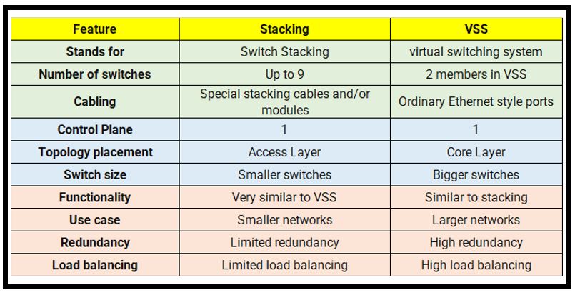
| Feature | Switch Stacking | VSS |
|---|---|---|
| Full Form | Switch Stack | Virtual Switching System |
| Switch Type | Fixed switches | Chassis switches |
| Maximum Devices | Multiple switches | Usually 2 switches |
| Connection | Stack cable | VSL link |
| Used In | Access layer | Core/Distribution layer |
| Distance | Short | Longer |
| Examples | 9200, 9300, 3850 | 6500, 6800 |
| Main Purpose | Port expansion and easy management | High availability and core redundancy |
Conclusion
Switch stacking is mainly used to combine multiple access switches for easier management and scalability. VSS is used to combine two high-end core switches for redundancy and nonstop network operation. Both technologies make multiple switches behave as one logical device, but they are designed for different network environments and requirements.
How to Make Switch Cable Connection Stacking and VSS
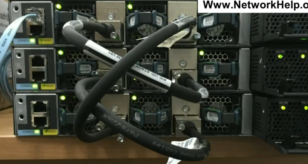
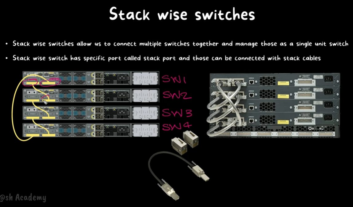
- In switch stacking, switches are connected using special stacking cables. These cables connect dedicated stack ports present on the switches. The stack ports create a high-speed communication path between all switches in the stack.
- For example, in Cisco Catalyst 9300 switches, special StackWise cables are used for stacking. These cables are different from normal Ethernet cables because they provide much higher bandwidth and low latency communication.
Basic Stack Cable Connection
Suppose there are three switches:
- Switch 1
- Switch 2
- Switch 3
Each switch has stack ports. The switches are connected one after another using stack cables.
Here:
- Stack port of Switch1 connects to Switch2
- Stack port of Switch2 connects to Switch3
This creates stack communication between all switches.
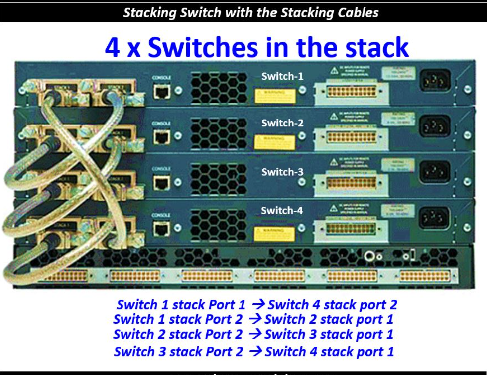
Ring Topology Connection
Most Cisco stack switches use ring topology for better redundancy. In this design, the last switch also connects back to the first switch.
					   Switch1 -------- Switch2
      |               |
      |               |
   Switch4 -------- Switch3
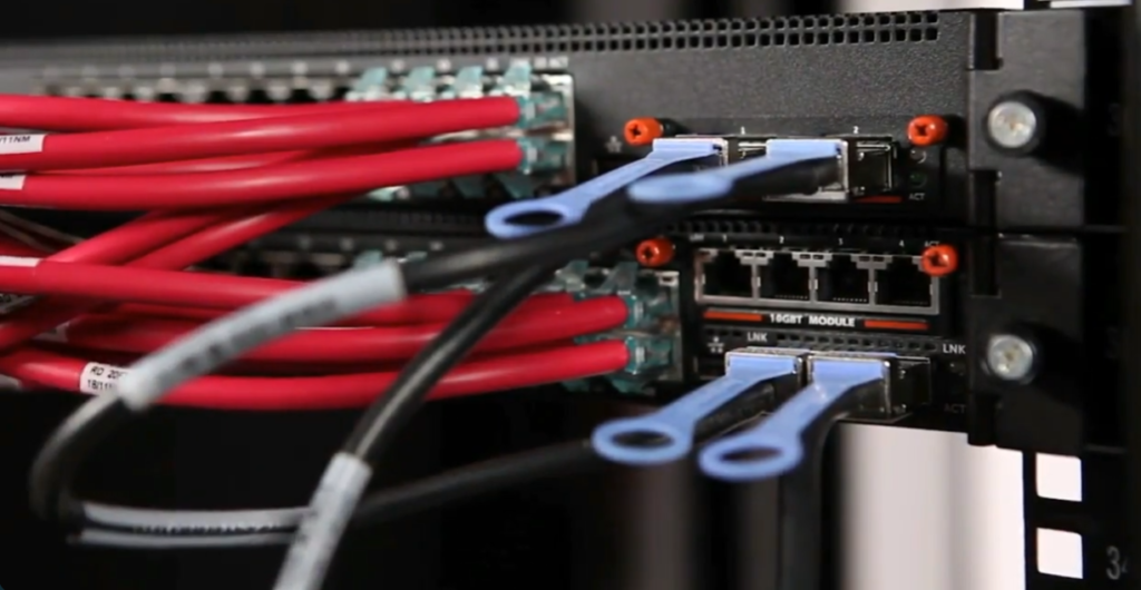
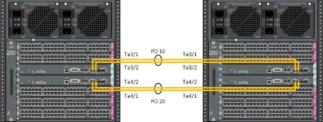
VSS Cable Connection
In VSS, normal stack cables are not used. Instead, high-speed Ethernet fiber links are used as Virtual Switch Links (VSLs).
Example with two Cisco Catalyst 6509 switches:
					Core Switch1 ======== Core Switch2
          (VSL Links)
The VSL links synchronize:
- Configuration
- Routing tables
- MAC address tables
- Traffic forwarding information
Usually multiple fiber links are bundled together using EtherChannel for higher bandwidth and redundancy.
Important Rules for Stack Cabling
When connecting stack cables:
- Use supported Cisco stack cables only
- Use compatible switch models
- Maintain correct stack topology
- Power off switches if required during installation
- Verify stack ports after connection
Incorrect cabling may prevent stack formation.
Checking Stack Connection
After connecting cables, administrators can verify stack status using Cisco CLI commands.
					show switch
show switch stack-ports

These commands display:
Stack members
Master switch
Port status
Stack link condition
Conclusion
Switch stacking uses dedicated stack cables and stack ports to connect multiple switches into one logical unit. Most Cisco switches use ring topology for redundancy and high-speed communication. In contrast, VSS uses high-speed Ethernet fiber links called VSLs to connect two chassis switches. Proper cable connection is very important for stable stack operation and network reliability.
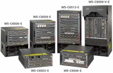
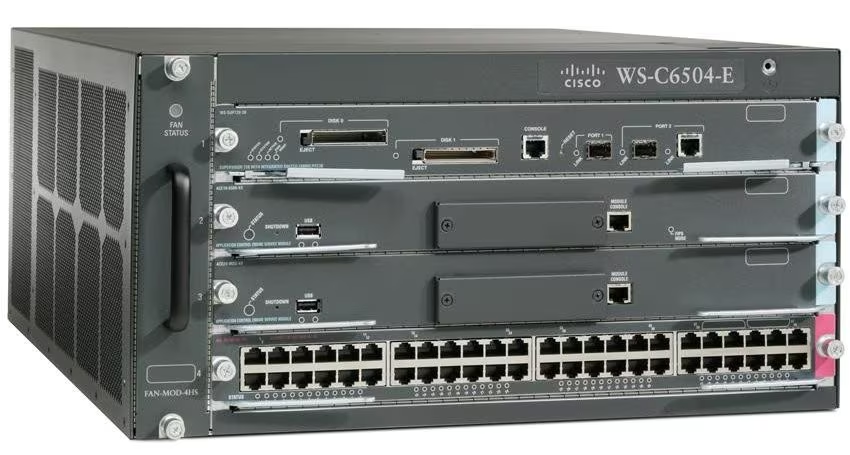
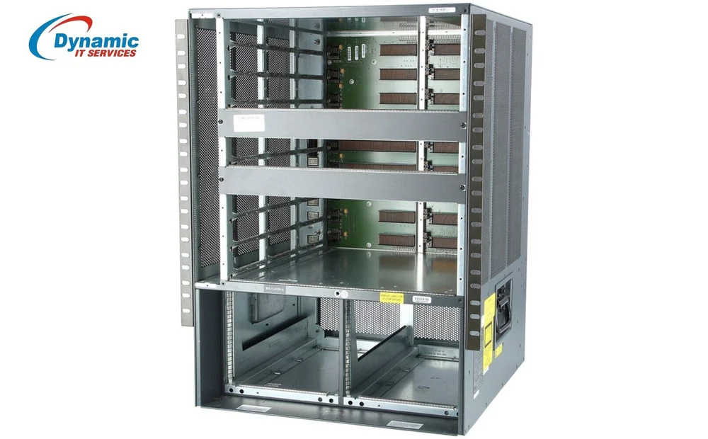
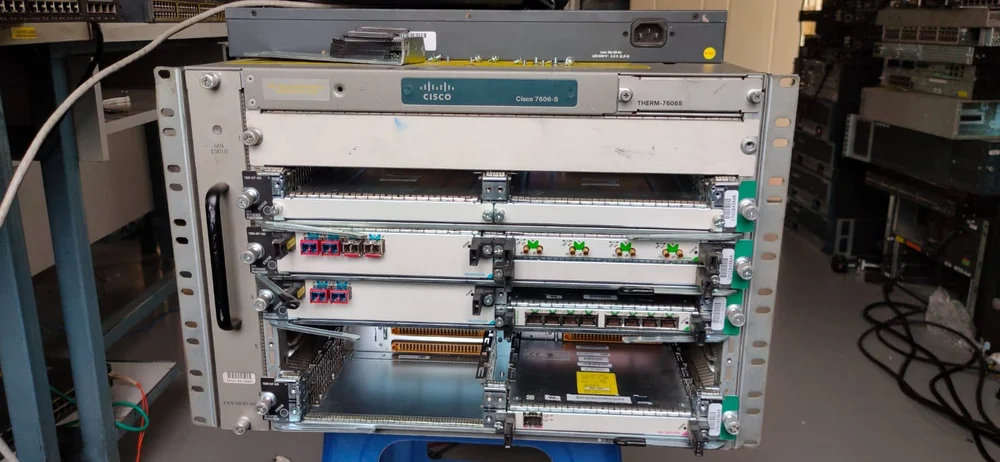
Cisco Catalyst 6500 Series Switches
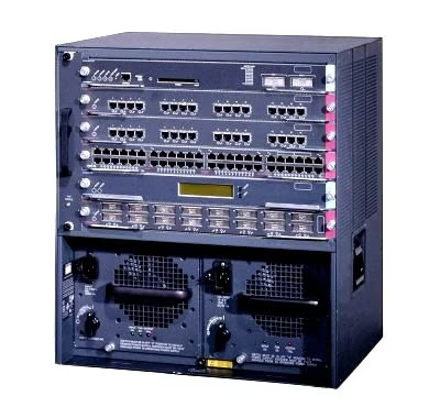
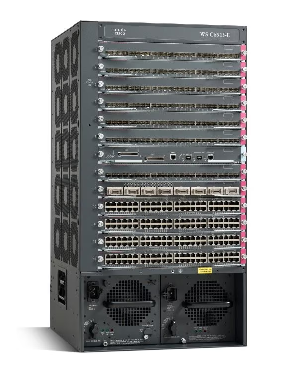
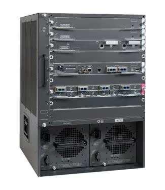
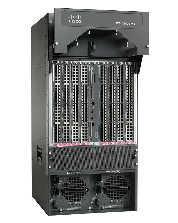
Cisco Catalyst 6500 Enhanced Series 9-Slot Chassis
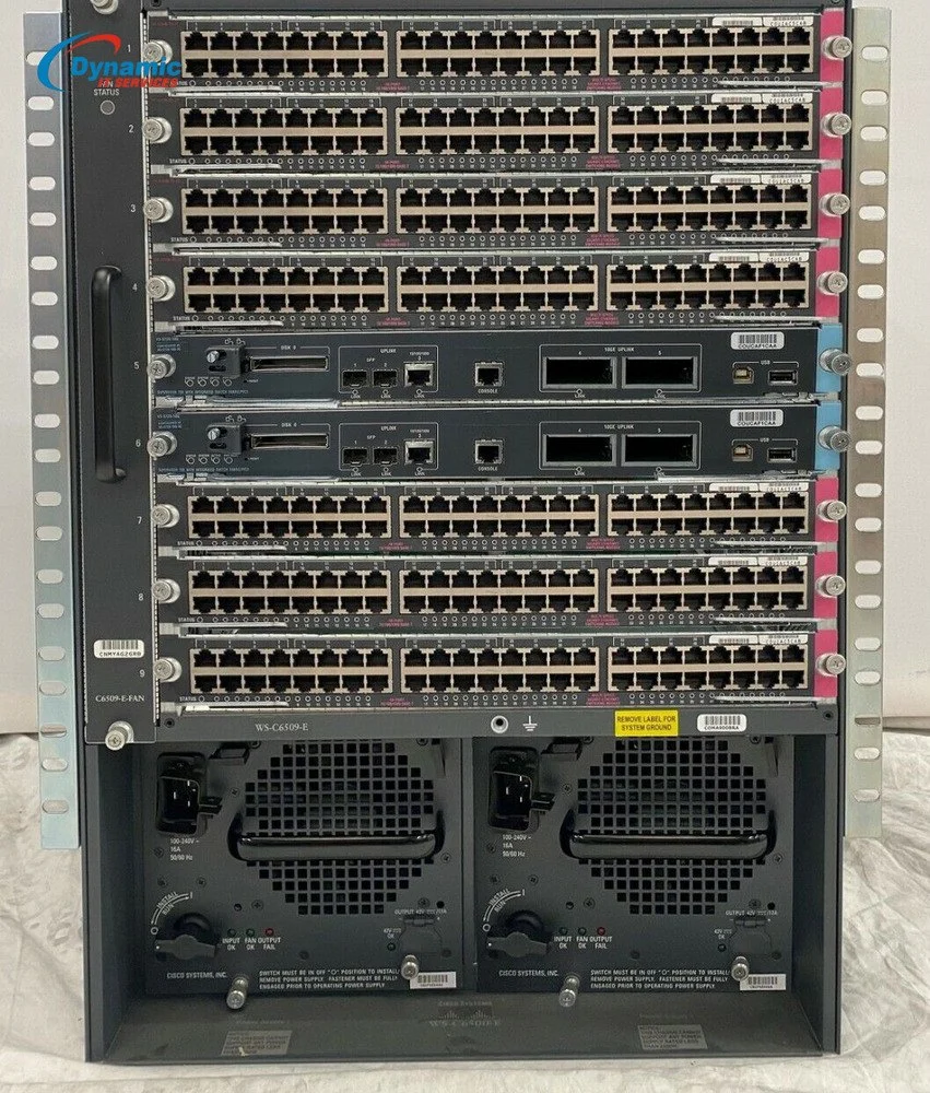
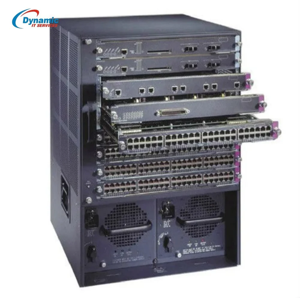
Cisco 6500 Switches VSS Example
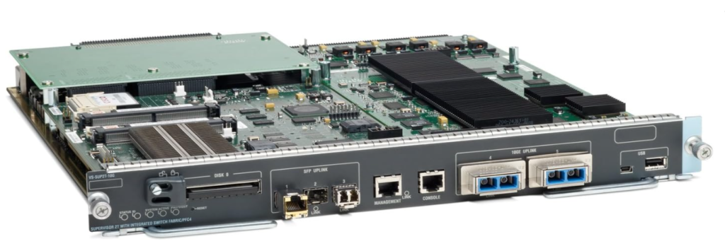
Cisco VS-S2T-10G-XL Catalyst 6500 Series Supervisor Engine 2T XL
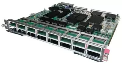
Cisco Catalyst 6500 16x 10G X2 Fibre Switch Line Card WS-X6716-10G-3C Price 42000
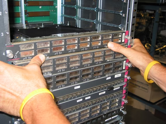


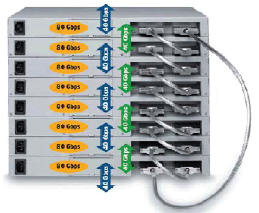
High Performance Stacking 40 Gbps Ethernet Capacity