
Build an ESP32 Home Automation with Web Server & EEPROM
Build an ESP32 home automation system with Web control, manual switches, EEPROM relay memory, and real-tme status dashboard.
Are you looking to automate your home using a smart and affordable IoT solution? This step-by-step guide will show you how to build a reliable ESP32 Home Automation system that features a responsive web dashboard, EEPROM memory storage for relay states, and support for both web-based and physical control using switches. With this setup, you can control your home appliances like lights, fans, or sockets from anywhere on your Wi-Fi network.

Project Key Features
- Web-Based Dashboard: Accessible from any browser on the same Wi-Fi network using ESP32’s static IP (e.g., 192.168.1.100).
- Real-Time Control: Instantly switch relays ON or OFF from the dashboard.
- EEPROM State Memory: Relay states are stored in EEPROM and restored on reboot.
- Physical Switch Integration: Works with both push buttons or latched switches.
- Responsive UI: Built with Bootstrap for compatibility with mobile and desktop screens.
- EEPROM Toggle: A button on the web UI lets you enable or disable the EEPROM state-saving feature.

How the ESP32 Project Works
All OFF Function: A single button on the dashboard turns OFF all relays instantly.
Web Server Setup: The ESP32 hosts a web server on a fixed IP (e.g., 192.168.1.100). Users can access the dashboard using any browser within the same network.
Relay Control: Four relays are connected to the ESP32. Each one can be toggled via the web interface or physical buttons.
EEPROM Memory: If EEPROM restore is enabled, the last known states of relays are saved to memory and automatically restored after a reboot or power cut.
Switch Handling: Latched or push-button switches are mapped to GPIOs and monitored using the AceButton library for accurate state changes.

Range of the ESP32 Home Automation Project
In this project, the Wi-Fi router is the hub, and the ESP32 acts as a Wi-Fi client. So, improving the router’s coverage and signal quality is the best way to increase the range and reliability of your ESP32 home automation system.
Wi-Fi Router Range Factors:
- Router Strength: The Wi-Fi range is primarily defined by your Wi-Fi router’s signal strength and quality.
- Router Placement: Central, elevated, and open placement of the router gives better signal coverage.
- Obstructions: Walls, metal objects, and thick construction materials block Wi-Fi signals and reduce range.
- Antenna Type: Though secondary, an ESP32 with an external antenna may get a stronger signal from the router.
- Power Supply: A stable power source ensures the ESP32 keeps a strong connection with the router.
Required Components:
- ESP32 DevKIT V1 Amazon
- 4-channel 5V SPDT Relay Module Amazon
- Latched switches or Push buttons
Circuit of the ESP32 Web Server project
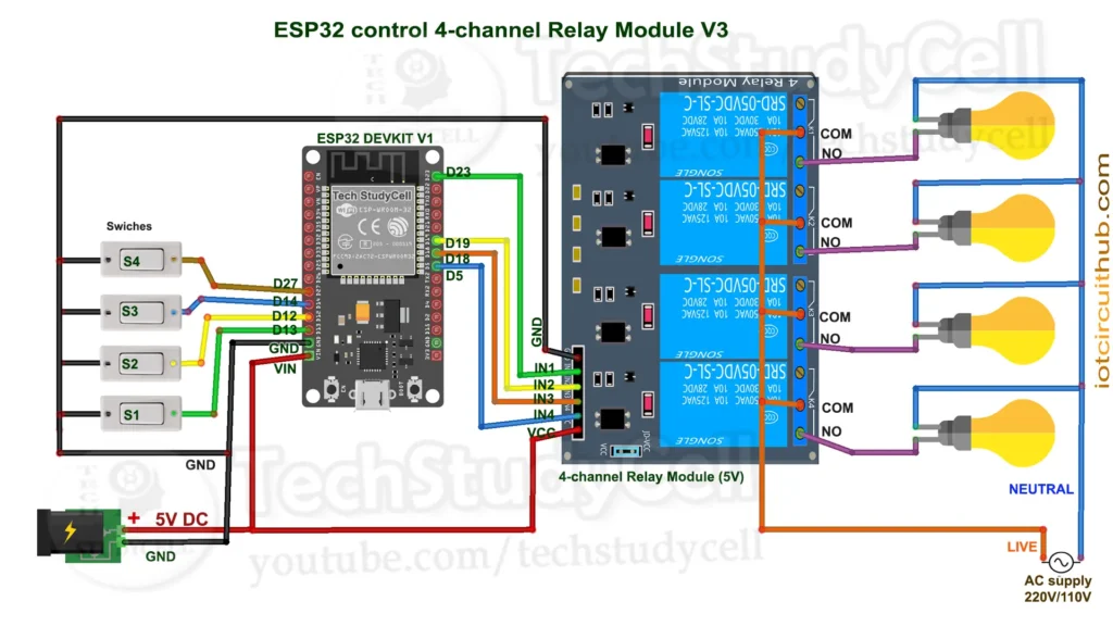
The circuit is very simple, I have used D23, D19, D18 & D5 GPIO to control the 4-channel relay module.
And, the GPIO D13, D12, D14 & D27 are connected with switches to control the relay module manually.
If you want to use push buttons for manual control, then refer to the following circuit diagram.

I have used the INPUT_PULLUP function in Arduino IDE instead of using the pull-up resistors with each push button.
As per the source code, when the control pins of the relay module receive a LOW signal, the relay will turn on, and the relay will turn off for the HIGH signal in the control pin.
I have used a 5V 5Amp mobile charger to supply the circuit.
Please take proper safety precautions while connecting the AC appliances.
Program ESP32 with Arduino IDE
In the tutorial video, I explained all the steps for programming the NodeMCU using Arduino IDE.
- Update the Preferences –> Aditional boards Manager URLs: https://dl.espressif.com/dl/package_esp32_index.json, http://arduino.esp8266.com/stable/package_esp8266com_index.json
- Then install the ESP32 board (version: 3.2.0) from the Board Manager, or Click Here to download the ESP32 board.
- You need the following libraries:
- WiFi
- WebServer
- AceButton (1.10.1)
Source Code for the ESP32 Web Server Relay Project
					/**********************************************************************************
 *  TITLE: Web Server + Manual Switch control 4 Relays using ESP32 WiFi router (Real time feedback + EEPROM)
 *  Click on the following links to learn more.
 *  YouTube Video: https://youtu.be/f9u0eUMsOfY
 *  Related Blog : https://iotcircuithub.com/esp32-home-automation-with-web-server-eeprom/
 *
 *  This code is provided free for project purpose and fair use only.
 *  Please do mail us to techstudycell@gmail.com if you want to use it commercially.
 *  Copyrighted © by Tech StudyCell
 *
 *  Preferences--> Aditional boards Manager URLs :
 *  https://raw.githubusercontent.com/espressif/arduino-esp32/gh-pages/package_esp32_dev_index.json, http://arduino.esp8266.com/stable/package_esp8266com_index.json
 *
 *  Download Board ESP32 (3.2.0) : https://github.com/espressif/arduino-esp32
 *
 *  Download the libraries:
 *  AceButton Library (1.10.1): https://github.com/bxparks/AceButton
 *
 * Here are the steps to use the code:
 *
 * Install Dependencies: Ensure the ESP32 board is added to Arduino IDE and install the WiFi and WebServer libraries if not pre-installed.
 * Configure Pins: Connect the four relay modules to GPIO pins 23, 19, 18 and 5 (active low).
   Connect four pushbuttons to GPIO pins 13, 12, 14 and 27.
 * Upload Code:Copy the code into the Arduino IDE, connect your ESP32, and upload the code.
 * Connect to ESP32 Wi-Fi: On a Wi-Fi-enabled device, connect to the router WiFi network with the SSID and password.
 * Access the Web Interface: Open a web browser and go to the fixed IP address 192.168.1.100 (http://192.168.1.100).
   You will see buttons to control each relay, a "EEPROM Restore" toggle button to active/deactivate EEPROM.
 * Control Relays: Use the buttons on the page to turn relays ON/OFF.

 **********************************************************************************/

#include <WiFi.h>
#include <WebServer.h>
#include <AceButton.h>
#include <EEPROM.h>
using namespace ace_button;

// Relay & Button pins
const int relayPins[] = {23, 19, 18, 5};
const int buttonPins[] = {13, 12, 14, 27};
const int numRelays = 4;
bool relayStates[numRelays] = {false, false, false, false};

const int eepromLed = 2;   //D2

const int EEPROM_SIZE = 64;
const int EEPROM_FLAG_ADDR = 0;
const int EEPROM_STATE_ADDR = 1;
bool eepromRestoreFlag = false;

// AceButton objects
ButtonConfig buttonConfigs[numRelays];
AceButton buttons[] = {
  AceButton(&buttonConfigs[0]),
  AceButton(&buttonConfigs[1]),
  AceButton(&buttonConfigs[2]),
  AceButton(&buttonConfigs[3])
};

// WebServer instance
WebServer server(80);

// Fixed IP configuration
IPAddress local_IP(192, 168, 1, 100);
IPAddress gateway(192, 168, 1, 1);
IPAddress subnet(255, 255, 255, 0);

// WiFi credentials
const char* ssid = "";  //WiFi Name
const char* password = "";  // WiFi Password

// ========== EEPROM ==========

void saveRelayStates() {
  for (int i = 0; i < numRelays; i++) {
    EEPROM.write(EEPROM_STATE_ADDR + i, relayStates[i]);
  }
  EEPROM.commit();
}

void loadRelayStates() {
  for (int i = 0; i < numRelays; i++) {
    relayStates[i] = EEPROM.read(EEPROM_STATE_ADDR + i);
  }
}

void saveRestoreFlag() {
  EEPROM.write(EEPROM_FLAG_ADDR, eepromRestoreFlag);
  EEPROM.commit();
}

void loadRestoreFlag() {
  eepromRestoreFlag = EEPROM.read(EEPROM_FLAG_ADDR);
}

// ========== Setup ==========

void setup() {
  Serial.begin(115200);
  EEPROM.begin(EEPROM_SIZE);

  // Load EEPROM restore flag & relay states
  loadRestoreFlag();
  if (eepromRestoreFlag) {
    loadRelayStates();
    Serial.println("Restored relay states from EEPROM");
  }

  // Connect WiFi with fixed IP
  WiFi.config(local_IP, gateway, subnet);
  WiFi.begin(ssid, password);
  Serial.print("Connecting to WiFi");
  while (WiFi.status() != WL_CONNECTED) {
    delay(500); Serial.print(".");
  }
  Serial.println("\nConnected!");
  Serial.print("ESP IP: "); Serial.println(WiFi.localIP());

  // Initialize relay pins
  for (int i = 0; i < numRelays; i++) {
    pinMode(relayPins[i], OUTPUT);
    digitalWrite(relayPins[i], relayStates[i] ? LOW : HIGH);
  }

  // Initialize buttons
  for (int i = 0; i < numRelays; i++) {
    pinMode(buttonPins[i], INPUT_PULLUP);
    buttons[i].init(buttonPins[i]);
  }

  pinMode(eepromLed, OUTPUT); // Initialize LED
  digitalWrite(eepromLed, LOW);

  // Attach button handlers (latched mode)
  buttonConfigs[0].setEventHandler(button1Handler);
  buttonConfigs[1].setEventHandler(button2Handler);
  buttonConfigs[2].setEventHandler(button3Handler);
  buttonConfigs[3].setEventHandler(button4Handler);

  // Web routes
  server.on("/", handleRoot);
  server.on("/toggle", handleToggle);
  server.on("/status", handleStatus);
  server.on("/alloff", handleAllOff);
  server.on("/eepromflag", handleEEPROMFlag);

  server.begin();
  Serial.println("Web Server started");
}

// ========== Loop ==========

void loop() {
  server.handleClient();

  // Check buttons
  for (uint8_t i = 0; i < numRelays; i++) {
    buttons[i].check();
  }
  digitalWrite(eepromLed, eepromRestoreFlag);
}

// ========== Button Handlers (Latched Mode) ==========

void button1Handler(AceButton* button, uint8_t eventType, uint8_t buttonState) {
  switch (eventType) {
    case AceButton::kEventPressed:
      relayStates[0] = true;
      digitalWrite(relayPins[0], LOW);
      break;
    case AceButton::kEventReleased:
      relayStates[0] = false;
      digitalWrite(relayPins[0], HIGH);
      break;
  }
}

void button2Handler(AceButton* button, uint8_t eventType, uint8_t buttonState) {
  switch (eventType) {
    case AceButton::kEventPressed:
      relayStates[1] = true;
      digitalWrite(relayPins[1], LOW);
      break;
    case AceButton::kEventReleased:
      relayStates[1] = false;
      digitalWrite(relayPins[1], HIGH);
      break;
  }
}

void button3Handler(AceButton* button, uint8_t eventType, uint8_t buttonState) {
  switch (eventType) {
    case AceButton::kEventPressed:
      relayStates[2] = true;
      digitalWrite(relayPins[2], LOW);
      break;
    case AceButton::kEventReleased:
      relayStates[2] = false;
      digitalWrite(relayPins[2], HIGH);
      break;
  }
}

void button4Handler(AceButton* button, uint8_t eventType, uint8_t buttonState) {
  switch (eventType) {
    case AceButton::kEventPressed:
      relayStates[3] = true;
      digitalWrite(relayPins[3], LOW);
      break;
    case AceButton::kEventReleased:
      relayStates[3] = false;
      digitalWrite(relayPins[3], HIGH);
      break;
  }
}

// ========== Web Handlers ==========

void handleRoot() {
  String html = R"rawliteral(
<!DOCTYPE html>
<html>
<head>
  <title>ESP32 Home Automation</title>
  <meta name="viewport" content="width=device-width, initial-scale=1">
  <style>
    body { font-family: Arial, sans-serif; margin: 0; background: #f0f0f0; }
    h2 { text-align: center; padding: 20px 0; color: #333; }
    .grid { display: grid; grid-template-columns: repeat(auto-fit, minmax(150px, 1fr)); gap: 15px; padding: 0 20px; }
    .card { background: white; padding: 20px; border-radius: 10px; box-shadow: 0 2px 5px rgba(0,0,0,0.2); text-align: center; }
    .btn { padding: 10px 20px; border: none; border-radius: 8px; font-size: 16px; cursor: pointer; width: 100%; }
    .on { background: #28a745; color: white; }
    .off { background: #dc3545; color: white; }
    .alloff-btn { margin: 20px; padding: 15px; background: #007bff; color: white; border: none; border-radius: 8px; font-size: 18px; width: calc(100% - 40px); cursor: pointer; }
    .toggle-flag { margin: 20px; padding: 15px; background: #6c757d; color: white; border: none; border-radius: 8px; font-size: 18px; width: calc(100% - 40px); cursor: pointer; }
    .footer { text-align: center; padding: 15px; font-size: 14px; color: #666; }
  </style>
</head>
<body>
  <h2>ESP32 Home Automation</h2>
  <div class="grid">
    <div class="card"><button id="btn0" class="btn on" onclick="toggleRelay(0)">Relay 1</button></div>
    <div class="card"><button id="btn1" class="btn on" onclick="toggleRelay(1)">Relay 2</button></div>
    <div class="card"><button id="btn2" class="btn on" onclick="toggleRelay(2)">Relay 3</button></div>
    <div class="card"><button id="btn3" class="btn on" onclick="toggleRelay(3)">Relay 4</button></div>
  </div>
  <button class="alloff-btn" onclick="allOff()">ALL OFF</button>

  <button class="toggle-flag" onclick="toggleEEPROMFlag()">EEPROM Restore: <span id="flagState">{{EEPROM_FLAG}}</span></button>

  <div class="footer">Created by Tech Studycell</div>

<script>
function toggleRelay(id) {
  fetch('/toggle?relay=' + id).then(fetchStatus);
}

function allOff() {
  fetch('/alloff').then(fetchStatus);
}

function toggleEEPROMFlag() {
  fetch('/eepromflag').then(fetchStatus);
}

function fetchStatus() {
  fetch('/status')
    .then(response => response.json())
    .then(data => {
      for (let i = 0; i < 4; i++) {
        let btn = document.getElementById('btn' + i);
        if (data['relay' + i]) {
          btn.classList.remove('on');
          btn.classList.add('off');
          btn.textContent = 'Relay ' + (i + 1) + ' (ON)';
        } else {
          btn.classList.remove('off');
          btn.classList.add('on');
          btn.textContent = 'Relay ' + (i + 1) + ' (OFF)';
        }
      }
      document.getElementById('flagState').textContent = data['eeprom'] ? 'ON' : 'OFF';
    });
}

// Auto-refresh status every 2 seconds
setInterval(fetchStatus, 2000);
fetchStatus();
</script>
</body>
</html>
)rawliteral";

  html.replace("{{EEPROM_FLAG}}", eepromRestoreFlag ? "ON" : "OFF");
  server.send(200, "text/html", html);
}

void handleToggle() {
  if (server.hasArg("relay")) {
    int relay = server.arg("relay").toInt();
    if (relay >= 0 && relay < 4) {
      relayStates[relay] = !relayStates[relay];
      digitalWrite(relayPins[relay], relayStates[relay] ? LOW : HIGH);
      saveRelayStates();
    }
  }
  handleStatus();
}

void handleAllOff() {
  for (int i = 0; i < numRelays; i++) {
    relayStates[i] = false;
    digitalWrite(relayPins[i], HIGH);
  }
  saveRelayStates();
  handleStatus();
}

void handleEEPROMFlag() {
  eepromRestoreFlag = !eepromRestoreFlag;
  saveRestoreFlag();
  handleStatus();
}

void handleStatus() {
  String json = "{";
  for (int i = 0; i < numRelays; i++) {
    json += "\"relay" + String(i) + "\":" + (relayStates[i] ? "true" : "false") + ",";
  }
  json += "\"eeprom\":" + String(eepromRestoreFlag ? "true" : "false") + "}";
  server.send(200, "application/json", json);
}
1. Include Required Libraries
					#include <WiFi.h>
#include <WebServer.h>
#include <AceButton.h>
#include <EEPROM.h>
using namespace ace_button;
Explanation:
This block includes all the essential libraries needed for the project:
- WiFi.h allows the ESP32 to connect to a WiFi network.
- WebServer.h provides tools to host a simple HTTP server on the ESP32.
- AceButton.h simplifies detecting different types of button events like press, release, long press, etc.
- EEPROM.h is used for reading and writing small amounts of data to non-volatile memory, which helps us save relay states and restore mode preferences even after power loss.
using namespace ace_button; makes it easier to use classes and functions from the AceButton library without writing the full namespace each time.
2. Define Relay and Button Pins
					const int relayPins[] = {23, 19, 18, 5};
const int buttonPins[] = {13, 12, 14, 27};
const int numRelays = 4;
bool relayStates[numRelays] = {false, false, false, false};
Explanation:
This section defines hardware pin assignments and sets up relay states:
- relayPins[] holds the GPIO numbers connected to each of the four relays. These pins will be set to LOW to turn the relays ON because the relays are “active low.”
- buttonPins[] holds the GPIOs connected to manual toggle switches for each relay.
numRelays defines how many relays/buttons are present, which helps in iterating over them later in loops. - relayStates[] keeps track of the ON/OFF status of each relay in software. It starts with all relays OFF (false).
3. EEPROM and Status LED Settings
					const int eepromLed = 2;
const int EEPROM_SIZE = 64;
const int EEPROM_FLAG_ADDR = 0;
const int EEPROM_STATE_ADDR = 1;
bool eepromRestoreFlag = false;
Explanation:
This section sets up EEPROM usage and a visual LED indicator:
- eepromLed is the GPIO connected to an LED (often GPIO 2, onboard LED), which shows whether EEPROM restore mode is active.
- EEPROM_SIZE sets how much space we want to allocate for EEPROM usage.
- EEPROM_FLAG_ADDR is the memory address where the “restore mode” flag is stored (0 or 1).
- EEPROM_STATE_ADDR is where we begin storing the actual relay states.
- eepromRestoreFlag holds a boolean value in RAM indicating whether saved relay states should be loaded at boot.
4. Setup AceButton Objects
					ButtonConfig buttonConfigs[numRelays];
AceButton buttons[] = {
  AceButton(&buttonConfigs[0]),
  AceButton(&buttonConfigs[1]),
  AceButton(&buttonConfigs[2]),
  AceButton(&buttonConfigs[3])
};
Explanation:
Here, we create four AceButton objects, one for each button, and assign a configuration object (ButtonConfig) to each of them. These configuration objects allow each button to respond to specific events, such as press and release. This is critical for our “latched switch” style control, where pressing turns the relay ON and releasing turns it OFF.
5. WiFi Configuration and Web Server Setup
					WebServer server(80);
IPAddress local_IP(192, 168, 1, 100);
IPAddress gateway(192, 168, 1, 1);
IPAddress subnet(255, 255, 255, 0);
const char* ssid = "";
const char* password = "";
Explanation:
This sets up a simple web server and assigns a static IP configuration:
- server(80) creates an HTTP server listening on port 80.
- local_IP, gateway, and subnet define the static IP settings so your ESP32 always uses the same address on your local network.
- ssid and password should be replaced with your actual Wi-Fi credentials so the ESP32 can connect to your router. So here you have to enter the WiFi name (ssid) and password.
6. EEPROM Utility Functions
					void saveRelayStates() {
  for (int i = 0; i < numRelays; i++) {
    EEPROM.write(EEPROM_STATE_ADDR + i, relayStates[i]);
  }
  EEPROM.commit();
}

void loadRelayStates() {
  for (int i = 0; i < numRelays; i++) {
    relayStates[i] = EEPROM.read(EEPROM_STATE_ADDR + i);
  }
}

void saveRestoreFlag() {
  EEPROM.write(EEPROM_FLAG_ADDR, eepromRestoreFlag);
  EEPROM.commit();
}

void loadRestoreFlag() {
  eepromRestoreFlag = EEPROM.read(EEPROM_FLAG_ADDR);
}
Explanation:
These functions handle saving and retrieving data from EEPROM:
- saveRelayStates() writes the current ON/OFF status of all relays to EEPROM.
- loadRelayStates() reads previously saved states from EEPROM into the program so the same relay states can be restored after reboot.
- saveRestoreFlag() saves whether EEPROM restore mode is ON or OFF.
- loadRestoreFlag() loads that flag at boot time to decide whether to restore saved relay states.
7. Setup Function
					void setup() {
  Serial.begin(115200);
  EEPROM.begin(EEPROM_SIZE);

  loadRestoreFlag();
  if (eepromRestoreFlag) loadRelayStates();
Explanation:
In the setup() function:
Serial.begin(115200) starts serial communication for debugging.
EEPROM.begin(EEPROM_SIZE) initializes the EEPROM memory area.
The saved eepromRestoreFlag is read from EEPROM.
If the flag is true, it loads previously saved relay states so the system boots up in the same state it was in before power loss.
8. WiFi and Relay Initialization
					  WiFi.config(local_IP, gateway, subnet);
  WiFi.begin(ssid, password);
  while (WiFi.status() != WL_CONNECTED) {
    delay(500); Serial.print(".");
  }
  Serial.println("\nConnected!");
  Serial.print("ESP IP: "); Serial.println(WiFi.localIP());
Explanation:
This code block connects the ESP32 to your Wi-Fi network using the static IP configuration. It waits in a loop until the Wi-Fi is connected, then prints the IP address on the serial monitor so you know where to access the web dashboard.
9. Set Relay and Button Modes
					  for (int i = 0; i < numRelays; i++) {
    pinMode(relayPins[i], OUTPUT);
    digitalWrite(relayPins[i], relayStates[i] ? LOW : HIGH);
  }

  for (int i = 0; i < numRelays; i++) {
    pinMode(buttonPins[i], INPUT_PULLUP);
    buttons[i].init(buttonPins[i]);
10. LED and Web Server Handlers
					 pinMode(eepromLed, OUTPUT);
  digitalWrite(eepromLed, LOW);

  buttonConfigs[0].setEventHandler(button1Handler);
  buttonConfigs[1].setEventHandler(button2Handler);
  buttonConfigs[2].setEventHandler(button3Handler);
  buttonConfigs[3].setEventHandler(button4Handler);

  server.on("/", handleRoot);
  server.on("/toggle", handleToggle);
  server.on("/status", handleStatus);
  server.on("/alloff", handleAllOff);
  server.on("/eepromflag", handleEEPROMFlag);

  server.begin();
  Serial.println("Web Server started");
}
11. Loop Function
					void loop() {
  server.handleClient();
  for (uint8_t i = 0; i < numRelays; i++) {
    buttons[i].check();
  }
  digitalWrite(eepromLed, eepromRestoreFlag);
}
12. Button Handlers (Latched)
					void button1Handler(...) {
  if (eventType == AceButton::kEventPressed) {
    relayStates[0] = true; digitalWrite(relayPins[0], LOW);
  } else if (eventType == AceButton::kEventReleased) {
    relayStates[0] = false; digitalWrite(relayPins[0], HIGH);
  }
}
13. Web Handler Functions
					void handleToggle() {
  int relay = server.arg("relay").toInt();
  if (relay >= 0 && relay < 4) {
    relayStates[relay] = !relayStates[relay];
    digitalWrite(relayPins[relay], relayStates[relay] ? LOW : HIGH);
    saveRelayStates();
  }
  handleStatus();
}
All OFF
					void handleAllOff() {
  for (int i = 0; i < numRelays; i++) {
    relayStates[i] = false;
    digitalWrite(relayPins[i], HIGH);
  }
  saveRelayStates();
  handleStatus();
}
EEPROM Flag Toggle
					void handleEEPROMFlag() {
  eepromRestoreFlag = !eepromRestoreFlag;
  saveRestoreFlag();
  handleStatus();
}
Relay Status in JSON
					void handleStatus() {
  String json = "{";
  for (int i = 0; i < numRelays; i++) {
    json += "\"relay" + String(i) + "\":" + (relayStates[i] ? "true" : "false") + ",";
  }
  json += "\"eeprom\":" + String(eepromRestoreFlag ? "true" : "false") + "}";
  server.send(200, "application/json", json);
}
Explanation:
Returns the current state of each relay and the EEPROM flag in JSON format. This is used by the web page’s JavaScript to update the UI in real-time without reloading the page.
This ESP32 Home Automation project demonstrates how to control relays both via a web interface and physical latched switches, with real-time feedback and EEPROM-based state restoration. It combines WiFi, web server, EEPROM, and button handling using the AceButton library, making it a robust and reliable smart home solution.
How to Connect to the IP and Test the Project
Once you have successfully uploaded the code to your ESP32 board using the Arduino IDE, follow these steps to connect and test the project:
1. Power the ESP32 and Open Serial Monitor
- After programming, power the ESP32 via USB or external 5V source.
- Open the Serial Monitor in Arduino IDE (baud rate:
115200). - Then press the reset button (EN).
- Wait a few seconds to see messages like:
Connecting to WiFi.... Connected! ESP IP: 192.168.1.100 Web Server started
2. Note the IP Address
- The ESP32 connects to your Wi-Fi router using the fixed IP defined in the code:
IPAddress local_IP(192, 168, 1, 100); - Make sure your router supports this IP range. If your router has a different subnet, you may need to change this IP accordingly.

3. Connect Your Phone or PC to the Same Wi-Fi
- Your phone or PC must be connected to the same Wi-Fi network as the ESP32.
- This is important because the ESP32’s web server is accessible only within the same local network.
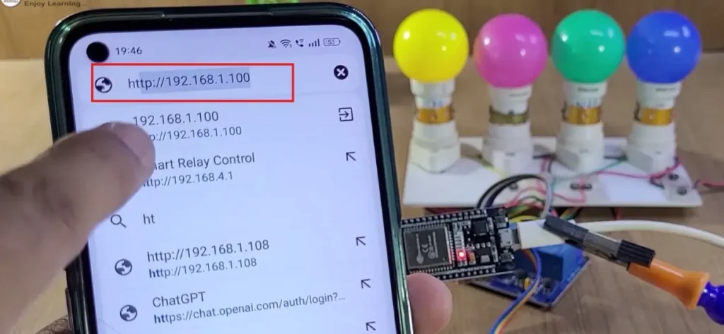
4. Open a Browser and Access the Web Dashboard
- Open any web browser (Chrome, Firefox, etc.).
- In the address bar, type:
http://192.168.1.100 - You should see the ESP32 Home Automation Dashboard with 4 buttons to control each relay, a button to turn All OFF, and a toggle to switch the EEPROM Restore flag.

5. Test the Relays and Buttons
- Click any Relay button on the web page. The corresponding relay should activate (ON) or deactivate (OFF).

- Press and release the physical switch connected to each GPIO (latched mode). Relay should stay ON while pressed and turn OFF when released.
- Click the “ALL OFF” button to instantly turn all relays OFF.
- Use the EEPROM Restore toggle to enable or disable state-saving across reboots.

6. Verify EEPROM Restore Feature
- Toggle the EEPROM flag ON from the dashboard.
- Turn ON any relays.
- Restart or power-cycle the ESP32.
- If the restore flag is active, the relays will resume their last saved state after reboot.
This process ensures that your ESP32 home automation setup is fully functional and can be controlled both physically and remotely via your local Wi-Fi network.